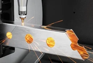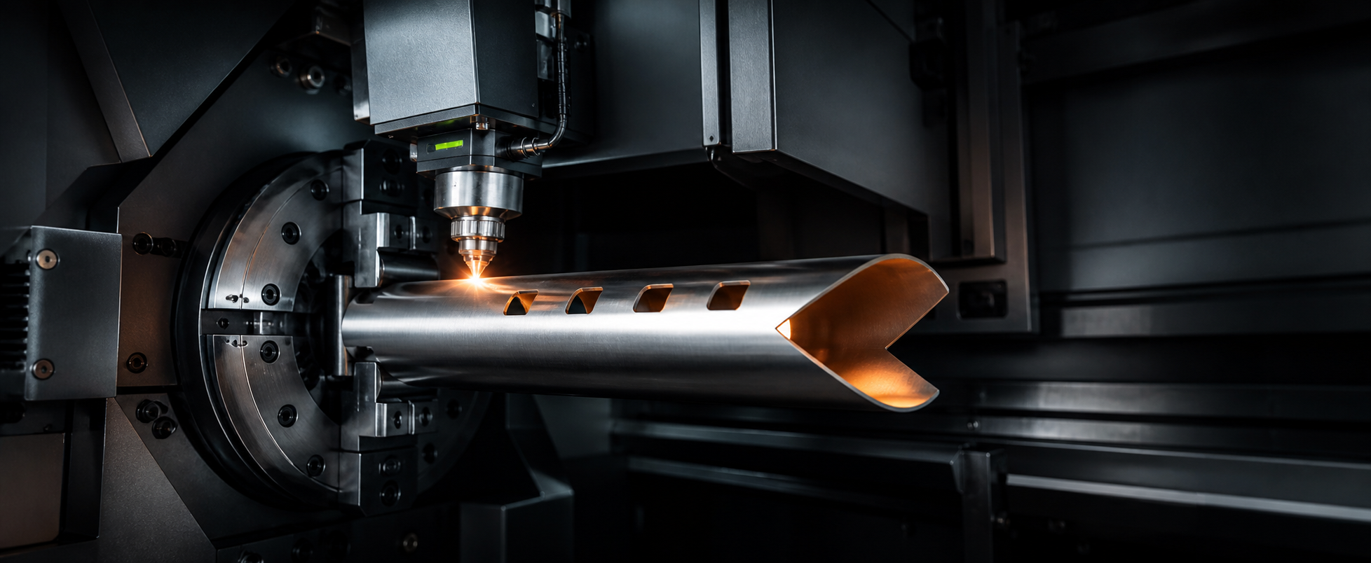
A tube feature is not production-ready simply because it can be modelled in CAD. Hole function, wall thickness, edge distance, profile shape, weld-seam position, cutting-head access, kerf, heat input and assembly fit all affect manufacturability.
Use the rules in this guide as preliminary DFM checks—not universal minimum dimensions. Final feasibility depends on the actual material, profile, feature location, machine configuration and required edge quality.
If the frame profile has not yet been selected, start with our round vs square vs rectangular tube comparison. Profile shape changes the available mounting faces, joint geometry, feature orientation and fixture strategy.
Tube laser cutting can combine cut-to-length work with holes, slots, notches, fish-mouths and features on several faces. Good design can reduce drilling, manual coping, repeated positioning and welding fixtures. Poor design can create trapped scrap, weak webs, inaccessible cuts or joints that look perfect in CAD but cannot be assembled reliably.
This tube laser cutting design guide is for engineers and procurement teams sourcing tubular parts, frames and welded assemblies in Singapore. It focuses on three-dimensional feature design rather than general file preparation. If you already have a STEP model and drawing, our metal tube laser cutting service in Singapore can review the proposed manufacturing route.
Do not apply one minimum-hole, minimum-slot or assembly-gap formula to every tube. Material, wall thickness, profile size, feature position, cutting direction, machine configuration and required function all affect the result.
Five Inputs to Confirm Before Designing Tube Features
The sixth input—function—is often the most important. A laser can create many geometries, but the correct production route depends on what the feature must do. Identify which characteristics locate the assembly, carry load, receive a fastener or remain cosmetic.
Designing Round Holes and Other Openings
Hole diameter alone does not determine feasibility. The supplier must consider wall thickness, material, curvature, corner proximity, piercing position, required edge condition and whether the hole is the final functional surface.
| Hole function | Laser-cut condition may be suitable for | Additional consideration |
|---|---|---|
| Clearance hole | Bolts, general fixings and access | Allow realistic assembly clearance and check local edge distance |
| Cable or ventilation opening | Routes and non-locating access | Specify deburring and safe edge requirements |
| Locating or dowel hole | Near-net opening or pre-location | Drilling or reaming may be required for the final fit |
| Bearing or precision bore | Initial material removal | Consider boring, reaming or CNC machining |
| Threaded feature | Pilot or access hole | Confirm tapping method, wall engagement and thread requirement |
| Hole on a curved face | General functional openings | Evaluate curvature, beam incidence and inspection method |
Do not use one universal minimum-hole formula
Rules based only on a hole-diameter-to-wall-thickness ratio can be useful as an early screening concept, but they are not a universal production guarantee. Final results vary with material, profile, cutting technology, parameters, feature location and quality requirement. Instead of forcing a formula onto the drawing, state the feature’s function and ask for DFM confirmation.
Keep critical holes away from uncertain geometry
Features close to a tube end, square-tube corner, formed radius or weld seam require extra review. The actual local surface may differ from the ideal CAD face. When a critical hole must be near one of these areas, give the supplier the assembly context and identify whether secondary machining is acceptable.
Slots, Edge Distance and Remaining Web
Slots are useful for fastener adjustment, cable routing, locating tabs and interlocking joints. Their manufacturability depends on more than slot width:
- Slot width relative to wall thickness and required edge condition.
- Slot length and its effect on local tube stiffness.
- End radius and whether the mating tab can seat fully.
- Distance from the tube end or a neighbouring cut.
- Remaining material between the slot and a corner or seam.
- Whether the cut-out can release safely or may remain trapped inside the tube.
Hole-to-end distance
A large opening close to a cut end can leave a narrow, flexible strip of material. That strip may distort during cutting, deburring, handling or welding. The acceptable distance depends on the opening, wall thickness, material and load path—not a single number applied to all profiles.
Hole-to-hole distance
Closely spaced holes or slots create a narrow bridge. This can accumulate heat, move after cutting or lose structural value. Increase the remaining web when the tube wall is thin, the openings are large, the area carries load or the feature is close to the end.
Features near square-tube corners
The corner is not an infinitely sharp CAD line. It has an outside and inside radius, and the flat-face width may vary. Avoid placing precision features where the cut would cross the changing corner geometry unless the design has been reviewed for that specific section.
Instead of asking, “Can you cut a 3 mm slot?”, explain the material, wall thickness, profile, slot function, mating-tab size and required assembly condition. That allows the supplier to evaluate the complete feature.
Locating Features on Multiple Faces
One advantage of tube laser processing is the ability to create coordinated features on different faces in a programmed operation. Those features still need a clear datum strategy.
- Round tube: define both axial position and angular clocking around the tube axis.
- Square tube: identify the reference face and the relationship between top, side and opposite-face features.
- Rectangular tube: make the width × height orientation unambiguous in the model and drawing.
- Special profile: supply the actual section information and a reference orientation.
Do not dimension each face independently if the assembly depends on their relationship. Use a common reference and indicate which relationships are critical. Raw-tube twist, corner geometry and weld-seam position also need consideration. For detailed specification and inspection guidance, read our tube laser cutting tolerance guide.
Fish-Mouths, Notches, Coping Features and Mitre Joints
Fish-mouth and coping geometry
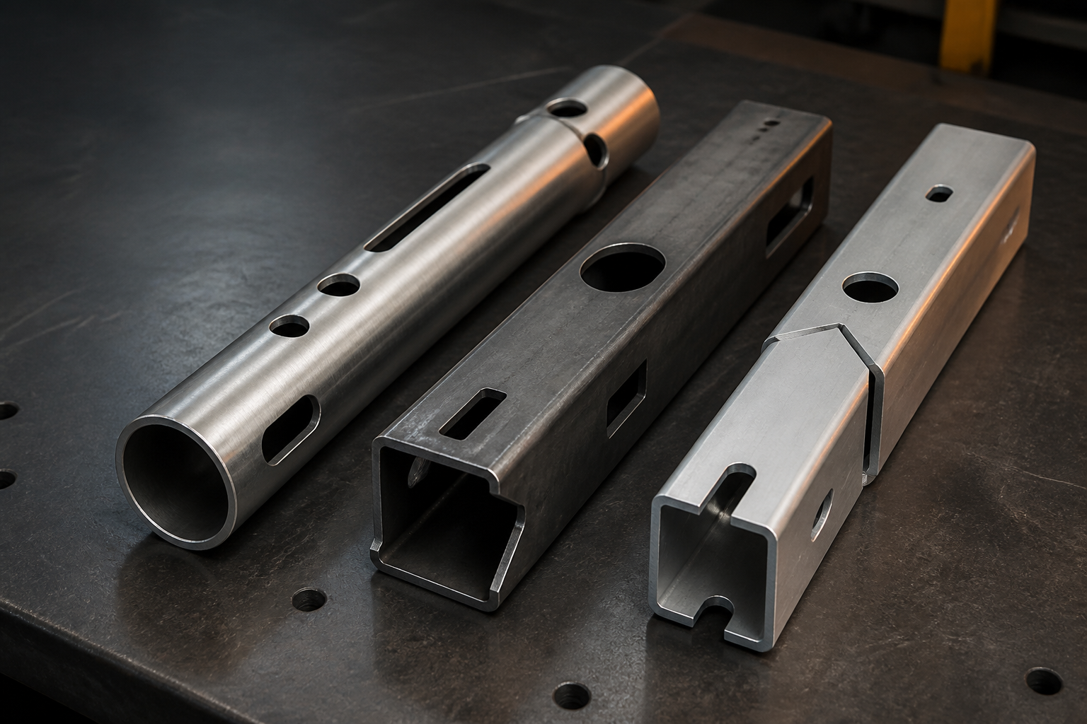
A fish-mouth or coping cut helps one tube fit against another. A direct Boolean subtraction in CAD may produce a visually exact, zero-clearance intersection, but real parts need an achievable fit. Consider kerf, tube-size variation, weld access, insertion direction, surface treatment and whether a small gap is needed for assembly.
Notches and reliefs
Notches can locate a cross-member, clear an obstruction or create a bend-and-fold concept in the tube wall. Check the notch root, remaining ligament and whether a sharp internal corner creates an unnecessary stress concentration. Also verify that the removed slug will separate without damaging the tube interior or machine.
Mitre joints
A simple mitre is different from a three-dimensional bevel or weld-preparation feature. Mark the functional requirement: mating angle, finished outside dimension, weld gap, bevel angle, root face or final contour. Do not rely on a visually angled CAD face to communicate welding intent.
2D versus 3D cutting
Many common tube features can be made with a 2D cutting head. Bevels, inclined edges and some complex joints may require a 3D cutting configuration. Capability is machine-dependent, and a 3D head is not automatically the best route for every wall thickness or feature. Ask the supplier to confirm cutting-head access and whether finishing is required.
Head access, collision clearance, effective thickness, profile rotation and the machine’s actual 2D or 3D configuration determine whether a bevel or complex joint is feasible.
Self-Locating Tabs and Slots
Tabs and slots can convert the tube itself into an assembly aid. They may reduce manual marking, prevent reversed orientation and help hold a frame before welding. They do not automatically eliminate fixtures or dimensional variation.
| Design objective | Possible approach | DFM check |
|---|---|---|
| Prevent reversed assembly | Use an asymmetric tab or slot pattern | Confirm that only the intended orientation can engage |
| Locate before welding | Use tabs to establish approximate position | Allow for welding access, gap and distortion |
| Identify similar parts | Use coded notch or tab patterns | Avoid weakening the functional area |
| Control insertion depth | Use a shoulder, stop tab or end feature | Check tolerance stack and surface finish |
| Reduce separate fixtures | Use interlocking geometry | Verify stability throughout the welding sequence |
Specify the intended fit
“Tab fits slot” is not a complete requirement. State whether the joint needs a free slip fit, hand assembly, light retention or another controlled condition. The correct compensation depends on kerf, profile variation, cut-edge condition, coating or plating, assembly direction and required repeatability.
Do not copy a universal clearance value from another material or supplier. Ask the fabricator to apply suitable process compensation and confirm the fit using the actual design.
Welding Gap, Assembly Fit and Weld-Seam Position
Design the joint for the welding process
A zero-gap CAD intersection may be difficult to assemble, while excessive clearance can make location and weld consistency harder. The joint should provide:
- A practical insertion and assembly direction.
- Access for the selected welding process.
- An appropriate fit-up condition for the joint design.
- Space for coating or finishing where relevant.
- A strategy for distortion and critical post-weld dimensions.
If a hole or face must remain precise after welding, consider whether it should be drilled, reamed or machined after the assembly is welded. Tightening the pre-weld laser-cut tolerance may not control welding distortion.
For production planning beyond cutting, link the design to the intended welding and structural assembly process.
Control the supplied tube’s weld seam when it matters
The weld seam can have a different local thickness, surface condition and mechanical history from the rest of the tube. It may also be cosmetically undesirable on a visible face. If seam position affects cutting, bending, welding, appearance or load direction, show the required orientation on the drawing and include it in the RFQ.
Some industrial systems can detect and orient a weld seam, but that is an equipment-dependent capability. Do not assume automatic seam control. The supplier must confirm how the specified orientation will be managed for the actual profile.
STEP, DXF and PDF: What Should You Send?
| File | Primary use for tube parts | Important limitation |
|---|---|---|
| STEP | Three-dimensional profile, multi-face features, notches, mitres and assembly relationships | Does not replace controlled tolerance, material and inspection notes |
| DXF | Simple 2D profiles or geometry specifically requested by the supplier | Can lose face orientation, clocking and three-dimensional relationships |
| Material, revision, datums, tolerances, welding, finishing and inspection requirements | Not an efficient substitute for a programmable 3D model |
For tube parts with features on several faces, the preferred submission is normally a STEP model plus a controlled PDF drawing. The STEP model communicates three-dimensional geometry; the PDF defines what must be controlled and accepted.
Use our CAD file preparation guide for general drawing checks and our STEP vs IGES vs DXF guide for broader file-format selection.
Tube Design Pre-Submission Checklist
- Material grade, tube specification, outside size and wall thickness are stated.
- Round, square, rectangular or special-profile orientation is unambiguous.
- The STEP model and PDF drawing use the same revision.
- Critical holes, slots and joints are identified by function.
- Reference faces, tube axis and rotational clocking are defined where required.
- Openings do not leave an obviously fragile web near an end, corner or another cut.
- Cut-out slugs and internal scrap have a practical release strategy.
- Fish-mouth, notch and mitre geometry includes the intended assembly fit.
- Tabs and slots specify assembly direction and required fit condition.
- Welding access, joint gap and post-weld critical dimensions have been reviewed.
- Weld-seam orientation is specified if it affects function or appearance.
- Bevel and 3D cutting requirements are clearly identified.
- Drilling, reaming, tapping, machining and finishing are listed.
- Quantity, inspection requirements and Singapore delivery needs are included.
If you are still deciding between processes, read Tube Laser Cutting vs Saw Cutting. For machine frames, guarding and automation structures, see our industrial automation application support.
Frequently Asked Questions
What is the minimum hole size for laser-cut tube?
There is no universal minimum hole size. It depends on material, wall thickness, profile geometry, feature position, cutting parameters and required edge quality. Treat any diameter-to-thickness rule as an initial DFM screen and confirm the actual feature with the supplier.
Can a tube laser cut holes on multiple faces?
Industrial tube laser systems can process features on several faces when the profile, machine configuration and feature access permit. The model and drawing should clearly define face orientation, rotational clocking and critical relationships.
How should I design tabs and slots for tube frames?
Define the assembly direction, required fit, welding access, surface finish and whether the feature prevents incorrect orientation. Do not use one universal tab-to-slot clearance for every material and supplier.
Can tube laser cutting make fish-mouth and mitre joints?
Many fish-mouths, notches and mitres are suitable for tube laser cutting. Complex bevels or inclined edges may require 3D cutting capability. The supplier should confirm head access, wall thickness, fit and finishing requirements.
Should I send STEP, DXF or PDF files?
For multi-face tube parts, send a STEP model plus a controlled PDF drawing. Use STEP for 3D geometry and PDF for material, datums, tolerances, welding and inspection requirements. DXF may be sufficient only for simpler geometry or a supplier-specific workflow.
Does the tube weld seam affect hole and notch placement?
It can. Seam position may affect local geometry, cutting behaviour, appearance, bending, welding or structural requirements. If it matters, specify the required orientation and ask how the supplier will control it.
Sources and Technical Context
- BLM Group ArTube: 3D tube CAD/CAM, feature feasibility and weld-seam management
- BLM Group: 3D model import, joints, welding and tube programming
- BLM Group: weld-seam position in tube processing
- Bystronic Tube Expert Guide: 2D and 3D tube-cutting context
Send Your Tube Design for a DFM Review
Share the STEP model, PDF drawing, tube specification and quantities. Lumen Future can review holes, slots, notches, joints, secondary operations and inspection requirements before quotation.