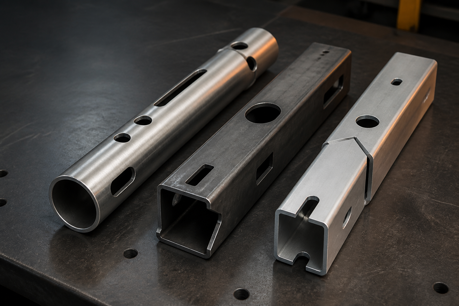
Tube laser cutting does not have one universal tolerance. Cut length, hole size, hole position, rotational alignment, multi-face feature position and end squareness are separate requirements. Each is influenced by profile shape, wall thickness, raw-material condition, chucking, support, cutting strategy, datum selection and inspection method.
A machine positioning specification is therefore not the same as a guaranteed tolerance on the finished part. For a reliable quotation, identify the functional characteristics on the drawing and ask the supplier to confirm them against the actual tube and production route.
Buyers often ask, “What accuracy can a tube laser hold?” The better question is, “Which characteristic must be controlled, relative to what datum, and how will it be measured?” A clearance hole, a locating slot, a cut end and a feature on the opposite face do not present the same manufacturing or inspection problem.
This guide explains how to specify and evaluate tube laser cutting tolerances for round, square and rectangular profiles. It is intended for engineers and procurement teams sourcing frames, guards, brackets, machine structures and tubular assemblies in Singapore. For a project review, see our metal tube laser cutting service in Singapore.
Machine accuracy, controller resolution and finished-part tolerance are not interchangeable. A production tolerance should be confirmed against the actual material, profile size, wall thickness, feature location, datum scheme and inspection plan.
Why There Is No Single Tube Laser Cutting Tolerance
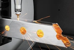
A tube laser system coordinates linear feed, rotation and the cutting path. Modern industrial systems can process round, square and rectangular tubes as well as selected open or special profiles. That capability does not create one tolerance value that applies to every feature or every profile.
A published machine figure may describe positioning or repeatability under defined test conditions. The finished component additionally reflects the actual tube geometry, how the stock is supported and clamped, thermal cutting conditions, feature location, part length and measurement setup. Even two dimensions on the same part may need different tolerances because they serve different functions.
| Requirement | What it controls | Typical functional reason |
|---|---|---|
| Cut length | Distance between finished ends | Frame size, stack-up and assembly envelope |
| Hole or slot size | Diameter, width and local feature geometry | Fastener clearance, cable routing or location |
| Feature position | Location from a datum or another feature | Alignment with mating components |
| Rotational position | Angular location around the tube axis | Orientation of holes and multi-face features |
| End squareness | End orientation relative to the tube axis | Butt joints, welding and seating |
| Multi-face alignment | Relationship between features on different faces | Brackets, frames and cross-member assembly |
For a wider buyer-level explanation covering flat parts and general laser cutting, read our laser cutting tolerance guide. This page focuses specifically on the extra variables created by tubular profiles and rotational processing.
Six Tolerances Buyers Should Specify Separately
1. Cut length tolerance
Cut length normally means the distance between the two finished ends, but that definition becomes ambiguous when an end is angled, contoured or fish-mouthed. The drawing should identify the points, planes or datums from which length is evaluated. On long components, raw-tube bow, support and thermal conditions may contribute to the final result.
Do not assume the feed-axis specification is the guaranteed end-to-end part tolerance. Confirm the finished length requirement and whether deburring, facing, welding or subsequent machining changes the acceptance condition.
2. Hole and slot size
Laser cutting can efficiently produce clearance holes, slots and access features in a tube wall. Their final geometry can be influenced by wall thickness, piercing conditions, material, assist gas, local heat input and the relationship between the beam and a curved surface.
A feature that is suitable for a bolt clearance may not be suitable for a dowel, bearing or close sliding fit. Specify the functional fit instead of applying the tightest tolerance to every opening. Slot-end geometry and minimum webs near a cut end should also be reviewed during DFM.
3. Hole and feature position
Position must be defined from a meaningful reference. A hole can meet its diameter requirement while being incorrectly located relative to the tube end, centreline, mounting face or another hole. Chain dimensioning can accumulate variation and obscure the functional relationship.
For mating features, identify the datum structure and distinguish critical positions from general dimensions. If a feature is only for ventilation or cable access, an unnecessarily tight positional tolerance may add inspection and manufacturing cost without improving function.
4. Rotational or angular alignment
Round tube introduces a degree of freedom that a flat sheet does not: the feature can move around the tube axis. Two holes can have the correct axial spacing but the wrong angular relationship. A clocking datum, seam orientation, flat, reference hole or other repeatable feature may be needed to define rotation.
On square and rectangular tube, rotation appears as face orientation and twist. The drawing should clearly name or identify the top, side and reference faces when features occur on more than one face.
5. Multi-face feature position
Tube laser cutting can consolidate holes, slots, notches and contours on several faces into one programmed operation. The critical requirement is often the relationship between those features rather than the individual size of each feature.
Square and rectangular hollow sections have corner radii, possible twist and dimensional variation. A top-face hole measured independently may pass inspection while its relationship to a side-face slot causes an assembly problem. Use a common datum scheme when cross-face alignment is functional.
6. End squareness, mitres and bevels
Separate a perpendicular cut, a simple mitre, a weld-preparation bevel and a three-dimensional intersection. They require different geometry and may require different equipment capability. A nominal angle alone may not control the actual seating or weld gap.
State whether the requirement is end squareness, angularity, profile of the cut contour or fit-up against a mating tube. If weld preparation is required, identify the intended joint and confirm whether a secondary finishing operation is needed.
Round vs Square vs Rectangular Tube
| Profile | Main tolerance risks | Drawing priority |
|---|---|---|
| Round tube | Ovality, rotational clocking, seam direction and curved-surface feature geometry | Define the tube axis, angular reference and feature position |
| Square tube | Corner radius, twist, face identification and cross-face relationship | Identify faces and establish a common datum system |
| Rectangular tube | Width-height orientation, long-face flexibility, twist and support | State width × height orientation and functional mounting face |
| Special or open profile | Asymmetric clamping, local deformation and non-standard section geometry | Provide the section standard, STEP model and actual profile information |
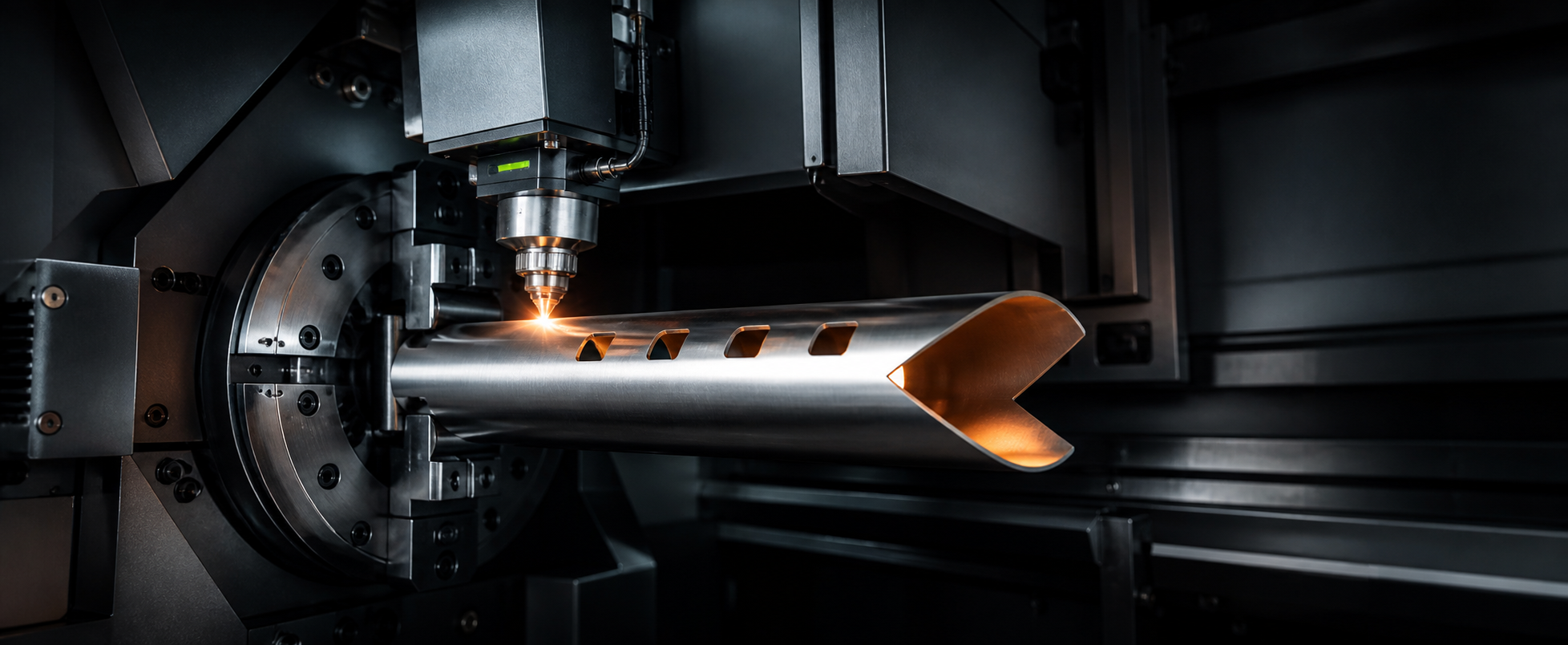
Round profiles can be rotated continuously, but a meaningful angular reference is required when the part has clocked features. Square and rectangular profiles provide physical faces, yet their corner radii and twist mean those faces are not perfect mathematical planes. Special profiles require an early feasibility review because loading, clamping and support may be different from standard closed sections.
Industry equipment documentation confirms that tube laser systems can handle several profile families; it should not be used as proof that every supplier, machine or profile has the same capacity or guaranteed result. Always submit the actual cross-section and part geometry for review.
How Raw Material Affects Finished-Part Accuracy
A CAD model represents ideal geometry. Production equipment processes real tube with permitted manufacturing variation. Relevant inputs include:
If weld-seam orientation is important to appearance, bending, welding or feature placement, state it in the RFQ. Do not assume the seam will automatically be located on a particular face or angular position.
Chucking, Rotation and Support
Tube processing coordinates several sources of motion. Their interaction matters more than a single specification:
- Chucking: clamping must resist motion without unnecessarily deforming a thin-wall profile.
- Rotation: angular positioning affects clocked holes and features on multiple faces.
- Feed: axial positioning affects cut length and feature distance from the end.
- Support: long or flexible profiles need controlled support to reduce sag and movement.
- Cutting strategy: piercing order, heat distribution and feature sequence can affect local condition.
- Repositioning: if the part is re-clamped or transferred to another operation, the datum must be recreated.
Do not copy a machine brochure’s positioning value into the title block of a production drawing. Ask for confirmation of the actual critical characteristics after material, profile, quantity and inspection requirements are known.
When Drilling, Reaming or CNC Machining Is Still Needed
Tube laser cutting can create an efficient near-final feature, but the laser is not automatically the finishing process for every functional interface.
| Feature | Laser-cut condition may be suitable for | Consider secondary machining when |
|---|---|---|
| Round hole | General clearance, cable access and ventilation | Dowel, bearing, precision fit or controlled cylindricity is required |
| Threaded feature | Creating a pilot or access opening | A specified thread form and engagement are required |
| Tube end | Weld fit-up or general assembly | A precision seating face, flatness or surface finish is required |
| Slot or key feature | Locating tabs and general assembly clearance | A close sliding fit or specific edge finish is required |
| Post-weld hole | Pre-positioning or access | Final position must be held after welding distortion |
A practical route may be laser cutting for length, contours and general holes, followed by drilling, boring, reaming, tapping or CNC machining only where the function requires it. This avoids applying precision-machining cost to every feature.
How to Dimension a Tube Drawing
- Identify the stock. State material grade, profile type, outside size, wall thickness and governing material standard where applicable.
- Choose the functional primary datum. This may be a mounting face, tube axis or another stable feature—not simply the easiest edge to dimension.
- Define the axial reference. Identify the end or plane from which feature positions and part length are evaluated.
- Control rotation. For round tube, define clocking. For square and rectangular tube, identify the reference face.
- Dimension critical features from datums. Avoid long chains of dimensions where accumulated variation would affect assembly.
- Separate functional and general dimensions. Apply tighter requirements only where the design needs them.
- State seam requirements. Identify whether the weld seam must avoid a feature, face or visible area.
- Define the inspection state. Clarify whether acceptance is after cutting, finishing, welding or final assembly.
“All dimensions ±0.1 mm” with chained hole dimensions, no face identification and no rotational datum.
Identify the functional datum faces or axis, control the critical hole pattern from those datums, specify rotation where needed, and leave non-critical dimensions under a realistic general tolerance agreed with the supplier.
ASME Y14.5 provides an established language for communicating datum reference frames, feature relationships and tolerance zones. Use the drawing standard required by your organisation or project, and make sure the inspection approach matches the stated requirements. For feature-level DFM, see our guide to designing tube holes, slots, notches and joints. For file preparation, use our CAD file preparation guide and STEP vs IGES vs DXF comparison.
What Should a Tube Inspection Report Include?
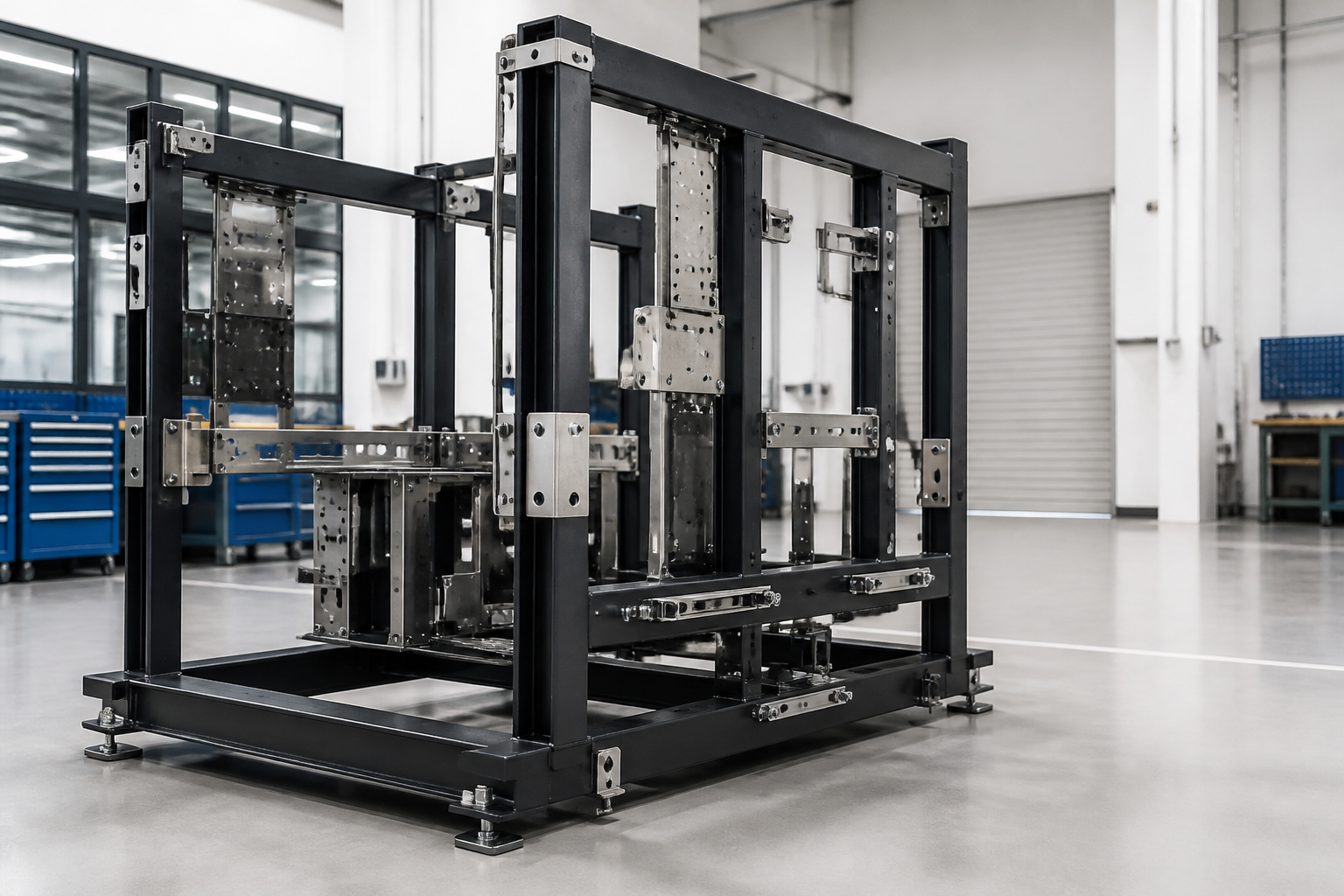
The inspection plan should follow the drawing and purchasing requirement. A full dimensional report or CMM report should not be assumed to be included with every order; request the required documentation during quotation.
- Part number, revision and drawing reference.
- Material or batch identification when required.
- Critical characteristic and associated datum reference.
- Specified limit, measured result and acceptance decision.
- Inspection quantity or sampling plan.
- Measurement equipment or method used.
- Inspection date and relevant process stage.
- Any agreed deviation, rework or concession reference.
Depending on the feature, inspection may use calipers, height gauges, pin gauges, angle measurement, optical measurement, dedicated fixtures or coordinate measurement. The method must be capable of referencing the part consistently without distorting a thin-wall profile. Learn more about Lumen Future’s quality assurance and dimensional inspection approach.
Tube Laser Cutting RFQ Checklist
- Round, square, rectangular, open or special profile.
- Exact material grade and relevant material standard.
- Outside diameter or width × height.
- Nominal wall thickness.
- Part length and quantity, including expected repeat demand.
- STEP model for multi-face geometry.
- PDF drawing with datums and critical dimensions.
- Hole, slot, notch, mitre and end-profile requirements.
- Rotational alignment and weld-seam orientation requirements.
- Required deburring, finishing, welding or secondary machining.
- Inspection method, sampling and report requirements.
- Required delivery location and schedule in Singapore.
If the manufacturing route is still undecided, compare tube laser cutting vs saw cutting. Simple cut-to-length parts may suit sawing, while parts with coordinated holes, slots, notches and multi-face features may benefit from tube laser processing. Tube frames for machinery and guarding can also be reviewed through our industrial automation application support.
Frequently Asked Questions
What tolerance can tube laser cutting achieve?
There is no universal value. The achievable and guaranteed tolerance depends on the characteristic being controlled, profile shape and size, material condition, wall thickness, feature location, setup, support and inspection method. Submit the actual drawing for confirmation.
Is round tube easier to cut accurately than square tube?
Not in every respect. Round tube rotates smoothly but needs a defined angular reference for clocked features and may have ovality. Square tube has identifiable faces but can have twist, corner-radius variation and cross-face alignment issues.
How is hole position measured on a round tube?
The drawing should define both axial position and angular position relative to a repeatable datum such as the tube axis, an end plane, seam direction, flat or reference feature. The inspection method must recreate those references consistently.
Does a weld seam affect tube laser cutting accuracy?
It can affect local geometry, material consistency, clamping or feature orientation depending on the tube and design. If seam position matters to cutting, welding, appearance or assembly, state the required orientation in the RFQ.
When should laser-cut holes be drilled or reamed?
Consider secondary machining for dowel holes, bearing fits, precision bores, threaded features or requirements involving controlled geometry and surface finish. General clearance and access holes may be suitable directly from laser cutting after review.
What files are needed for a tube laser cutting quotation?
Provide the profile specification, material, wall thickness, quantities, a STEP model for multi-face geometry and a PDF drawing showing datums, critical tolerances, secondary operations and inspection requirements.
Sources and Technical Context
- ASME Y14 standards: dimensioning, tolerancing and digital product definition
- ASME: datum reference frames, tolerance zones and verification context
- BLM Group: industrial processing of round, square, rectangular and special profiles
Need a Tolerance Review for a Tube Part?
Send the STEP model, PDF drawing, tube specification and quantities. Lumen Future can review critical features, datum strategy, secondary machining and inspection requirements before quotation.