For laser cutting in Singapore, your CAD file should be a 2D vector format (DXF preferred, then DWG, SVG, AI, PDF), drawn at 1:1 scale in millimetres, with closed paths, no duplicate or overlapping lines, splines converted to arcs, and cut, engrave, and score features on separate layers or colours. Remove all title blocks, dimensions, and annotations from the cut file itself. The most common reason files get rejected is open contours — gaps in the geometry where lines look connected but aren’t actually joined. A clean DXF helps your supplier respond faster; a messy one usually triggers back-and-forth emails that can add days to your project.
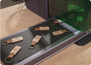
A typical scenario in Singapore industrial fabrication: an engineer sends what looks like a ready-to-cut DXF for a stainless steel bracket order. The drawing looks clean on screen and passes visual inspection. During actual cutting, however, the laser keeps stopping mid-path. Investigation often reveals invisible micro-gaps in the contour — vertices left disconnected from earlier sketch operations. Each gap forces the laser head to lift, re-position, and pierce again, leaving small marks at every gap and extending the cutting time. Most of these issues can be avoided with one CAD command (such as OVERKILL in AutoCAD) before exporting.
Most engineers and designers in Singapore prepare CAD files thinking they’re sending a drawing. They’re actually sending instructions to a machine that interprets every line, vertex, and layer literally. This guide explains what laser cutting workflows actually need — and how to give it to them from the major CAD packages (SolidWorks, Fusion 360, AutoCAD, Illustrator, Inkscape). Get this right and your quote comes back faster, your parts cut cleaner, and your project doesn’t bounce between revisions.
At Lumen Future, we review CAD files for laser cutting, bending, engraving, and finishing projects across Singapore — from single prototypes to recurring production batches. The guide below is what we typically share with new customers preparing their first RFQ.
If you’ve already prepared a file and just want a quick pre-submission check, our CAD file checklist for accurate quotes is the shorter checklist version. This guide goes deeper into the why and how.
Why CAD File Quality Matters More Than You Think
A poorly prepared CAD file costs you in three ways that aren’t always obvious until later:
- Quoting delay. A clean DXF can be reviewed and quoted faster because the geometry is unambiguous. A messy one requires manual inspection, geometry repair, sometimes redrawing — extending what could have been a same-day quote into back-and-forth across several days.
- Cutting time and surface defects. Open contours, duplicate paths, and stray vertices can cause the laser head to pause, retract, and re-pierce. Each re-pierce may leave a small mark on the cut edge — visible on visible-surface parts, problematic on assembly-critical edges.
- Dimensional drift. Wrong units (inches confused as mm), wrong scale, missed kerf assumptions — parts come out at sizes you didn’t specify. Often both supplier and engineer initially assume the other made the error.
The two-minute investment of cleaning up your DXF before sending eliminates most of this. The rest of this guide shows exactly how.
The 6 Accepted File Formats (Ranked)
Ranked by suitability for laser cutting
| Rank | Format | Use Case | Source Software |
|---|---|---|---|
| 1 ⭐ | DXF | Industry standard for 2D laser cutting | AutoCAD, SolidWorks, Fusion 360, Inkscape |
| 2 | DWG | AutoCAD native; accepted by most suppliers | AutoCAD |
| 3 | STEP / IGES | 3D files; only when bending, 3D geometry verification, or assembly review is required | SolidWorks, Fusion 360, Inventor |
| 4 | SVG | Common from design tools; good for non-metal cutting | Illustrator, Inkscape, Figma |
| 5 | AI | Adobe Illustrator native; widely accepted | Adobe Illustrator |
| 6 | PDF (vector) | Acceptable but less reliable; verify vector content | Any (export from CAD) |
Two notes on format choice:
- Use DXF unless you have a specific reason not to. It’s universal, lightweight, preserves geometry accurately, and works across all common laser cutting software. DXF saved in AutoCAD 2013 format (or earlier) is most widely compatible — newer versions sometimes cause compatibility issues with older laser CAM software.
- Send 3D STEP/IGES files only when the part has bends, 3D geometry that must be verified, or assembly review is needed. For pure flat cuts, 3D is unnecessary and can confuse some quoting workflows. For parts that will be bent after cutting, 3D STEP lets the supplier verify the bend geometry and calculate flat patterns correctly. See our CNC bending tolerance guide for why flat pattern accuracy matters.
Avoid raster formats (JPG, PNG, BMP) for cut files — they’re images, not vector geometry. A laser cutter can’t follow a raster image without a separate tracing step, which introduces errors and dimensional inaccuracy.
Common File Errors That Slow Down Your Quote
Most quote delays in Singapore laser cutting workflows trace back to a handful of recurring file problems:
Open Contours (Gap Issues)
Lines that look connected but aren’t actually joined. The CAM or nesting software may fail to recognise the contour as closed and treat it as an incomplete cut path. Caused by sketch operations that didn’t close properly, imported geometry with floating vertices, or trim/extend operations that overshot.
Duplicate or Overlapping Lines
Two lines drawn on top of each other. The laser may cut the same path twice, wasting time and potentially creating visible double-cuts on edges. Particularly common after copy-paste operations or merging geometry from multiple sources.
Wrong Units (Inches vs Millimetres)
Drawing in inches but the laser software interpreting as millimetres (or vice versa) produces parts at 25.4× the intended size — or 1/25.4×. Always verify units before export. Millimetres is the standard for industrial laser cutting in Singapore.
Splines Instead of Arcs
Splines are smooth mathematical curves. Some CAM systems approximate splines as a series of short line segments, which may increase file complexity or affect toolpath quality. For better predictability, convert splines to tangent arcs before exporting to DXF.
Embedded Text and Annotations
Title blocks, dimension lines, notes, and reference text inside the cut file can be interpreted as cut paths. The laser may try to cut your dimension callouts. Always remove or freeze annotation layers before exporting the cut file. Provide notes in a separate PDF if needed.
Not Sure If Your DXF Is Ready?
Send your file to us for a quick pre-submission review — we’ll flag open contours, duplicate lines, or other issues before they slow down your quote.
Send CAD File for Review →Geometry Requirements: Closed Paths, No Splines, No Overlaps
Three geometry rules that every laser-cuttable file should satisfy:
| Rule | Why It Matters | How to Verify |
|---|---|---|
| Closed paths | Open contours can’t be cut as a single continuous path | Use “Hatch” or “Boundary” tool in AutoCAD; “Region” in Inventor; “Join” in Illustrator |
| No duplicate entities | May cause double-cuts or machine confusion | Run OVERKILL in AutoCAD; “Delete duplicates” in Illustrator |
| No splines (use arcs) | CAM software may approximate splines as short segments, affecting toolpath quality | Use “Spline to Arc” conversion in CAD; or model with arcs from the start |
| All geometry on Z=0 | 3D depth values can confuse 2D laser CAM | “Flatten” operation in AutoCAD; explicitly project to XY plane |
| Single units (mm preferred) | Mixed units cause sizing errors | Set drawing units in CAD before drawing, not after |
The most insidious issue is the “almost-closed” contour — visible to your eye as one continuous outline, but actually containing 0.001 mm gaps that only become apparent when the cutting machine tries to follow the path. The fix in AutoCAD: select all geometry and run PEDIT → Multiple → Join with a small fuzz factor (e.g., 0.01 mm) — this connects near-touching endpoints automatically.
Layer & Colour Management for Cut, Engrave, and Score
If your part needs more than just cutting — engraving, scoring, or marking on the same piece — separating these operations into different layers or colours is essential. Without separation, the laser operator may see them all as the same instruction.
| Operation | Common Layer Name | Suggested Colour | What It Does |
|---|---|---|---|
| Cut (through) | CUT or LASER_CUT | Red | Cuts all the way through the material |
| Engrave (surface) | ENGRAVE or LASER_ETCH | Blue | Marks the surface without cutting through |
| Score (partial) | SCORE | Green | Light cut for folding lines or score marks |
| Reference / Construction | REF or CONSTRUCTION | Yellow | Not cut; for visual reference only |
Colour conventions vary between suppliers, so include a quick legend in your email or as a note in the file: “Red = cut, Blue = engrave, Green = score.” The laser operator will set the corresponding power and speed parameters based on this mapping.
For engraving applications in particular, the layer setup also tells the supplier whether you need annealing, white marking, or deep engraving on metal parts — see our laser engraving metal vs non-metal guide for which method to specify.
Export from SolidWorks: Step-by-Step
SolidWorks DXF Export Workflow
- Open the part. For sheet metal parts with bends, ensure the Flat Pattern feature is unsuppressed (right-click in feature tree → Unsuppress).
- Right-click the face to be cut → Select
Export to DXF/DWG. - Choose “Export Face/Loop” for a single flat profile, or “Export Flat Pattern” for sheet metal with bend lines.
- Set format to AutoCAD 2013 format DXF (or earlier — newer formats sometimes incompatible with laser CAM software).
- Confirm units are millimetres in the export dialog.
- Save and verify in a DXF viewer (LibreCAD or AutoCAD) before sending.
Common SolidWorks issue: bend lines exported to the same layer as cut lines. Configure the export to put bend lines on a separate layer (typically “BEND”) so the laser operator knows where the part will be folded later.
Export from Fusion 360: Step-by-Step
Fusion 360 DXF Export Workflow
- If you have a 3D body, right-click the face you want to cut →
Create Sketch. This projects the profile into a 2D sketch. - Inspect the sketch for closed profiles before exporting. Fusion 360 highlights closed regions with a coloured fill — if your profile doesn’t fill, there are open contours to fix.
- To fix open contours: use coincident constraints between endpoints, or apply Trim / Extend to connect disconnected segments. Confirm the profile is closed before continuing.
- Right-click the sketch in the browser tree →
Save As DXF. - Verify units: Go to
File → Document Settings → Unitsand confirm millimetres before sketching. - Watch for splines: Fusion 360 sometimes preserves splines in DXF export. Convert to arcs before export using the “Spline to Arcs” approximation if your supplier prefers arc-only geometry.
For sheet metal parts in Fusion 360, use the Sheet Metal workspace’s “Create Flat Pattern” function before exporting — otherwise the DXF will be the curved 3D projection rather than the unfolded flat shape.
Export from AutoCAD: Step-by-Step
AutoCAD DXF Export Workflow
- Draw in Model Space at 1:1 scale in millimetres (set via
UNITScommand before drawing). - Move all cut geometry to a single layer named CUT or LASER_CUT. Freeze or delete all other layers.
- Run
OVERKILLto remove duplicate entities. - Run
PEDIT→ Multiple → Join with fuzz tolerance 0.01 mm to convert disconnected segments into continuous polylines. - Verify all geometry is on Z=0: use the
FLATTENexpress tool, or set Z coordinates to 0 manually. - SAVEAS → choose AutoCAD 2013 format DXF (or any DXF version up to 2013 for maximum compatibility).
AutoCAD is the most flexible source software for laser cutting but also the easiest to send messy files from. The OVERKILL and PEDIT/Join steps are essential — they catch the invisible duplicate and near-touching geometry that derails the cutting process.
Export from Adobe Illustrator & Inkscape
Vector Design Tool Export Workflow
- Set document units to millimetres from the start. In Illustrator: Edit → Preferences → Units → General: Millimeters. In Inkscape: File → Document Properties → Default units: mm.
- Convert all text to outlines. In Illustrator: select the text, then
Type → Create Outlines(Ctrl+Shift+O / Cmd+Shift+O). In Inkscape: select the text, thenPath → Object to Path. This prevents font issues at the supplier’s end. - Use hairline stroke weight (or as specified by your supplier — many laser CAM systems accept any thin stroke, but some require 0.001 pt specifically). Heavy strokes can confuse some laser CAM software about whether the stroke or its centreline is the cut path.
- Remove any raster images, gradients, effects. Only solid vector outlines should remain in the final cut file.
- Use “Save As” with .AI or .SVG format, or export as DXF via File → Export → DXF (Illustrator: File → Export → Export As → DXF).
- Verify scale is 1:1 — Illustrator’s artboard sometimes scales graphics for display; always check actual dimensions at export.
Designer-source files most often go wrong on text and scale issues. Always outline all text before sending, and always verify the final part dimensions in the exported file before submitting.
Pre-Submission Checklist + What to Send With Your File
Before clicking “send” on your quote request, run through this checklist. Suppliers that receive complete information can review faster and quote more accurately.
The Cutting File Itself
- Format: DXF (AutoCAD 2013 format or earlier) preferred; SVG/AI acceptable for non-metal
- Units: Millimetres, 1:1 scale
- Closed paths: No gaps, no open contours
- No duplicates: Run
OVERKILLor equivalent - No splines: Converted to arcs
- Text outlined (if from Illustrator/Inkscape)
- Z = 0: No 3D depth values
- Layers organised: Cut/engrave/score separated
- No annotations: Title blocks, dimensions, notes removed
What to Send Alongside the Cutting File
- Material specification: grade, thickness, surface (e.g., “SS304 1.5 mm 2B finish”)
- Quantity: total pieces; specify if mixed quantities per design
- Tolerance requirements: default ISO 2768-m OK, or specify tighter for critical features
- Finishing requirements: standard deburring, brushed finish, mirror polish — see our polishing & deburring guide
- Downstream process: “Parts will be powder coated” / “Will be welded” / “Will be plated”
- Delivery target: event date or production start, if relevant for rush handling
- Reference drawing (PDF, optional but recommended): a separate PDF with dimensions and notes — kept separate from the DXF cutting file
A complete submission with cutting file + reference drawing + material + quantity + finishing typically receives a quote within one working day. Missing information adds at least one back-and-forth email per missing item.
Three categories worth keeping mentally separate when preparing an RFQ:
- Cutting file — the production-ready DXF/SVG containing only cut geometry
- Reference drawing — a separate PDF showing dimensions, tolerances, and notes for human review
- Quotation information — the textual email or RFQ form covering material, quantity, finishing, delivery
Frequently Asked Questions
What’s the best file format to send for laser cutting?
DXF is the industry standard for 2D laser cutting — universally accepted, lightweight, and preserves geometry accurately. Use DXF saved in AutoCAD 2013 format (or earlier) for maximum compatibility with laser CAM software. SVG and AI are acceptable alternatives, particularly for design-tool source files cutting non-metal materials. For parts with bends, send a 3D STEP file so the supplier can verify the bend geometry. Avoid raster formats (JPG, PNG) entirely — they’re images, not vector instructions.
Can I send a 3D STEP or SolidWorks part file directly?
Yes, especially for sheet metal parts that include bends. The supplier can extract the flat pattern from the 3D model and verify the bend geometry simultaneously. For pure 2D cuts (no bending), a clean DXF is usually faster to process. If your supplier offers instant online quoting, check what file types they accept — many instant systems prefer DXF for 2D and STEP for 3D.
Why do laser cutting suppliers prefer DXF saved in AutoCAD 2013 format instead of newer versions?
Older DXF versions are simpler and more widely compatible across laser CAM software, especially with shops that have older but reliable cutting equipment. Newer DXF versions (2018+) sometimes include features that older laser software can’t interpret, causing import errors. AutoCAD 2007 or 2013 DXF format is the practical sweet spot — modern enough to support polylines and necessary geometry, old enough to import cleanly across systems.
My CAD file looks fine but the supplier says there are “open contours” — what’s happening?
Almost certainly small (0.001–0.05 mm) gaps between line segments that look connected visually but aren’t actually joined. These come from sketch operations, trim/extend with the wrong endpoints, or imported geometry. Fix: in AutoCAD, run PEDIT → Multiple → Join with a fuzz tolerance of 0.01 mm. In Illustrator, select all and use Object → Path → Join. In Fusion 360, inspect the sketch profile — if it doesn’t fill with a coloured region, you have open contours. Use coincident constraints or Trim/Extend to close the geometry.
Should I include kerf compensation in my CAD file or let the supplier handle it?
Generally let the supplier handle it. Modern laser CAM software applies kerf compensation automatically based on material, thickness, and cutting parameters — different from what you might calculate manually. Draw your part at the final intended dimensions; the supplier’s CAM software will offset the cutting path inward by the appropriate kerf width. If you have unusually tight tolerance requirements, flag this in your RFQ so the supplier can verify kerf assumptions match your needs.
Can I upload a screenshot or photo of my design and get a laser cutting quote?
Not for accurate quoting or production. Raster images (JPG, PNG, photos) don’t contain vector instructions for the laser — they would need to be traced, which introduces dimensional errors. For preliminary discussion or visual reference, sure — but for the actual cutting file, you need a proper vector format (DXF, SVG, AI, etc.). If you only have a sketch or photo, a CAD draftsman can convert it for you (often a small additional fee), but the conversion is essential before cutting.
See How Files Become Cut Parts
Watch our process videos showing how DXF files become finished laser-cut parts — from upload through nesting, cutting, and quality check.
Watch Videos →More Reference Material
Visit our Download Center for capability brochures, material guides, and other reference documents useful for planning laser cutting and fabrication projects.
Visit Download Center →Upload Your DXF for a Faster Laser Cutting Quote
Three takeaways from this guide:
- DXF (AutoCAD 2013 format or earlier), 1:1 scale, millimetres — the universal starting point for any Singapore laser cutting RFQ.
- Closed paths, no duplicates, no splines, no annotations — the four checks that prevent most file issues.
- Send material + quantity + tolerance + finishing alongside the file — complete submissions get faster, more accurate quotes.