Replacement sheet metal covers can be difficult to specify when the original CAD file is missing. The old panel may have bent flanges, worn fixing holes or alterations made during maintenance. Copying its present shape without checking the mounting interface can reproduce the damage rather than restore the intended fit.
You can start an enquiry without CAD. However, fabrication still needs confirmed geometry, material and acceptance requirements. Photographs, measurements and old parts are starting references, not automatic substitutes for an approved production drawing.
Quick answer: Send photographs of the cover and its installation location, known dimensions, quantity and details of any damage. Lumen Future accepts old parts for replacement assessment and can measure a supplied physical part and prepare fabrication drawings. Missing or damaged features still need clarification, and the proposed drawing must be confirmed before production.
This guide is for maintenance and purchasing teams arranging replacement machine panels, access covers and similar components. It explains how to move from incomplete references to a drawing and, where appropriate, a sample-fit check.
Start With What You Have
You do not need to invent a CAD model before making contact. First identify the available evidence and its limitations. A complete old cover, a damaged sample and a photograph each answer different questions.
| Available reference | Useful information | What still needs confirmation |
|---|---|---|
| Complete old cover | Physical form, holes, folds and component relationships. | Whether its shape is undamaged, plus material and target fit. |
| Damaged cover | Surviving features and some mounting details. | Intended geometry in damaged or missing areas. |
| Photographs only | Visible layout, purpose and installation context. | Measured dimensions, thickness and hidden features. |
| Sketch with partial dimensions | Known interfaces and an initial layout. | Missing dimensions, references, orientation and tolerances. |
| Part from similar equipment | A comparison for an otherwise missing feature. | Whether the equipment model, revision and interfaces actually match. |
Include overall views and close-ups of fixing points, folds and damage. A ruler in a photograph provides context but does not remove perspective error or reveal an unseen return flange. Label units and provide measured dimensions separately.
Before sending an old part, agree its identity, condition, packaging and return arrangements. Flag an irreplaceable reference and any restriction on removing attachments or altering it. Sample receipt does not authorise straightening or destructive investigation.
Explain What the Cover Does
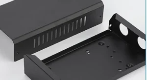
Describe what the component covers and how it is used. An appearance panel, removable access cover and protective enclosure can look similar but have different acceptance needs. Custom metal equipment covers should be specified by function as well as outline.
- Which surfaces or components does it attach to?
- Must it be removed regularly for maintenance?
- Are ventilation openings, gaskets, hinges or latches involved?
- Does it provide clearance for cables, connectors or moving equipment?
- Are there protective, sealing or electrical requirements that must be preserved?
Provide equipment identification and relevant existing specifications when available. An unexplained opening or asymmetric feature may be intentional; do not assume it can be removed or made symmetrical.
Matching the shape does not validate a safety function. If the cover has a protective or other safety-critical role, the equipment’s responsible party must define the design and acceptance requirements. A replacement that fits does not by itself establish equivalent guarding, sealing performance or equipment certification.
Confirm the Mounting Interface Before the Outer Shape
Start with the features that determine installation: the seating surface, fixing pattern, available internal space and surrounding obstructions. The outer perimeter matters, but it may not be the most reliable reference on a bent or corroded part.
Use a labelled sketch to identify the front, back and viewing direction. Make clear whether a dimension describes an internal opening, an external envelope or a distance between mounting features. Do not mix hole-centre dimensions with measurements to a hole edge.
- Fixing points: hole or slot sizes, centre locations and the relevant mating fasteners.
- Formed geometry: flange direction, height, offsets and required clear opening.
- Seating: surfaces that contact the equipment and any gasket or spacer arrangement.
- Access: room to insert and tighten fasteners, and remove the cover later.
- Adjacent features: hinges, latches, cables and other items that constrain the replacement.
Where the cover is unavailable or damaged, reliable measurements of the mating assembly can help establish the intended interface. Measurement access and responsibility must be agreed. Do not remove guards or reach into operating equipment to obtain dimensions; follow the equipment’s safe maintenance procedures.
For broader feature-design considerations, see the sheet metal laser cutting design guide. Keep finished-cover requirements distinct from the flat cutting geometry used to manufacture it.
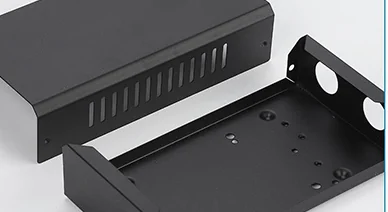
Do Not Copy Damage Into the Replacement
Keep three categories separate: measured condition, proposed replacement geometry and unresolved information. Measuring an old part accurately does not establish that every measured feature belongs in the new part.
Look for bent flanges, elongated holes, corrosion, missing corners and evidence of previous cutting or drilling. Ask whether the old cover fitted freely or required force when the fasteners were tightened. A distorted assembly interface may also need attention; replacing the panel alone does not necessarily resolve it.
Illustrative example: a worn fixing hole
Suppose one hole in an old access cover has become elongated. Its present boundary does not reliably establish the original hole diameter or centre. Review the mating fixing point, fastener and other sound references before proposing the replacement feature.
If a different hole or slot is proposed to address installation needs, record it as an approved change rather than an unnoticed copy of wear. This is a planning example, not a Lumen customer case or a universal repair instruction.
Similarly, do not automatically change an angled flange to 90 degrees. The angle may be intentional. Any inferred dimension should remain a question until there is an agreed basis for release.
Confirm Material, Thickness and Finish
Supply the known material grade and finish information. Appearance alone is not enough to identify a particular alloy or grade. Measurements through coating or at a corroded edge may also need interpretation before selecting nominal sheet thickness.
Do not assume a thicker replacement is always better. A thickness change can affect bend geometry, internal clearance, weight, fasteners and the relationship to adjacent parts. Material substitution or a structural change should be reviewed separately from like-for-like fabrication.
Identify the outward-facing surface, finish, grain direction where relevant and edge requirements. Show areas that must remain uncoated or retain a defined contact condition if the design requires them. Confirm whether original hardware is reused or new hinges, latches or inserts are included in the scope.
For appearance-sensitive equipment, agree the finish expectations rather than promising an exact match to an aged surface. Protecting the finished part during packaging should also form part of the handover requirements.
From a Physical Sample to an Approved Drawing
Lumen Future can receive an old cover, measure the supplied part and organise fabrication drawings for review. The measurement and drawing scope should be agreed for the actual component. This does not mean every missing original dimension can be recovered from a damaged sample, or that on-site surveying is automatically included.
- Review the references: identify the sample, available photographs, known dimensions and intended use.
- Record geometry and uncertainties: distinguish sound measured features from damage or missing information.
- Resolve the interfaces: confirm critical mounting dimensions and any required customer checks on the equipment.
- Prepare the proposed drawing: show formed geometry, material, thickness, finish and agreed acceptance requirements.
- Approve the release: confirm the drawing revision and close production-critical questions before fabrication.
The customer should identify the person who can approve target dimensions and changes. If the old part, sketch and mating assembly disagree, resolve that conflict explicitly. Do not let an assumption become a manufacturing instruction simply because it has been drawn in CAD.
A formed drawing or model communicates the finished cover; a cutting profile communicates the flat geometry used for manufacture. The manufacturing flat pattern should be prepared or checked through the agreed workflow, not guessed by adding flange lengths. The CAD file preparation guide explains final file-handover considerations once the geometry is established.
Fabricate and Check the Sample Against the Assembly
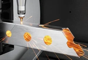
Sheet metal cover fabrication may combine sheet metal laser cutting for the profile and openings with CNC bending and folding for flanges and offsets. The approved drawing and quotation should define which operations, finishing and inspection are included.
A sample or first-piece fit check can be useful when the original design is uncertain or the mounting interface is newly confirmed. Agree whether trial fitting occurs before the remaining quantity is made and whether the sample represents the final finished condition.
- Does the cover enter the available space without unintended interference?
- Do fixing points align with the confirmed mating features?
- Are flanges clear of adjacent components?
- Can fasteners be installed and tightened as intended?
- Can the cover be removed for maintenance?
- Do the agreed edges, finish and appearance meet the requirements?
Where Lumen does not have the equipment or relevant mating parts, drawing-based inspection cannot demonstrate full installation fit. Agree who performs the actual trial fit and what feedback is required. Any separate functional or safety acceptance remains necessary.
Record changes arising from the trial and update the drawing revision. Keep the final approved record for repeat orders rather than relying only on the original damaged cover or a message saying “same as last time”.
What to Send for a Replacement Cover Enquiry
- Overall photographs of the old cover, including its reverse side and folds.
- Photographs of the mounting location and nearby components.
- Known dimensions, units and a labelled viewing direction.
- Fixing-hole, mating-interface and clearance requirements.
- Known material, thickness and surface-finish information.
- Details of damage, wear and previous modifications.
- Quantity, target timing and delivery location.
- Whether an old part or reliable physical reference is available.
- The contact who can confirm dimensions and arrange trial fitting.
Mark unknown information as unknown. Photos can support an initial review, but production scope and timing depend on resolving the geometry, drawing and acceptance requirements. Agree sample delivery before sending the only available reference.
Frequently Asked Questions
Can I request a replacement cover without a CAD file?
Yes. Lumen Future accepts old parts for replacement assessment and can measure a supplied physical sample and prepare fabrication drawings. The proposed geometry and requirements still need approval before production.
Are photographs enough to reproduce a metal cover?
Photographs help explain shape and installation, but usually cannot confirm all critical dimensions, thickness or hidden details. Measured information or a physical sample may be required. We do not promise precise replication from photographs alone.
Can a bent or damaged old cover be used as a reference?
It can provide useful surviving features. Damaged dimensions must be distinguished from the intended shape and checked against sound references or the mating assembly before release.
Should the replacement use the same material and thickness?
Confirm the original requirements and present use. A proposed substitute or thickness change needs review because it can affect fit, forming and function. It should not be made automatically.
Who checks whether the new panel fits the machine?
Agree this before fabrication. Lumen can inspect against the approved drawing; actual equipment fit must be checked by the agreed party with access to the assembly. Fitting correctly does not replace any required functional or safety assessment.
Start a Replacement Cover Review
Send photos of the old cover and its mounting location, known dimensions, quantity and whether a physical sample is available. We can review old-part measurement and drawing preparation alongside the cutting and bending requirements.