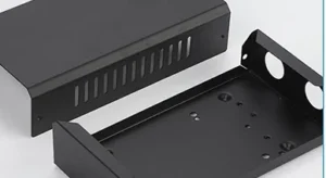
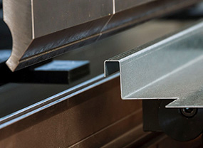
There is no single laser-cutting tolerance that applies to every material, thickness, part size and feature. Buyers should separate general profile dimensions from critical holes, slots, hole positions, edge taper, flatness and cosmetic requirements. A machine’s positioning accuracy or display resolution is not the guaranteed tolerance of the finished part. Specify only function-critical tolerances, identify the datum and measurement plane, and agree on the inspection method before production.
“Please cut accurately” is not an inspection requirement. Neither is a DXF file containing nominal geometry with no drawing notes. A supplier can manufacture the programmed outline correctly and still deliver a part that does not fit if the buyer has not defined which holes locate the assembly, which slot controls the mating tab, whether the upper or lower edge is measured, or whether flatness is part of acceptance.
This guide explains what Singapore buyers should specify when ordering laser-cut metal, acrylic and other sheet parts. It focuses on cut geometry and inspection; bending, welding and coating add further variation and must be reviewed as finished-fabrication requirements. For service selection and quotation basics, start with our laser cutting buyer’s guide.
What Should a Laser-Cut Drawing Control?
| Requirement | What it controls | Typical drawing method |
|---|---|---|
| Overall length and width | Finished external profile size | Linear dimensions with a general or individual tolerance |
| Hole diameter | Finished opening and fastener clearance | Diameter with an individual tolerance when functional |
| Slot width | Fit of tabs, fasteners or mating parts | Width, fit intent and measurement-plane note |
| Hole position | Assembly alignment and pattern relationship | Basic dimensions plus position control, or agreed coordinate tolerances |
| Profile location | Relationship of a contour to datums | Profile control or controlled coordinates |
| Edge taper | Difference through material thickness | Top/bottom size, wall-angle or perpendicularity requirement |
| Flatness | Out-of-plane condition of the sheet or part | Separate flatness specification and support condition |
| Edge quality | Burr, dross, striations, oxide and heat marks | Process note, visual limit or approved sample |
| Surface condition | Scratches, protective film and cosmetic finish | Cosmetic-face and handling specification |
| Inspection | How conformity is demonstrated | Instrument, sample size, datum and report requirement |
The most economical drawing usually combines a reasonable general tolerance for non-critical geometry with individual controls for features that affect fit, alignment, sealing or safety. Applying the tightest value to every dimension increases programming, process qualification, inspection and rejection risk without necessarily improving the assembly.
Machine Accuracy Is Not Finished-Part Tolerance
Machine brochures may list controller resolution, commanded increment, positioning accuracy or repeatability. These describe parts of the equipment’s motion system. They do not include every source of variation between a CAD line and the inspected edge of a production part.
A machine can repeat the same programmed path while the finished edge remains consistently offset because the kerf compensation, material response or measurement method is wrong. Conversely, a visually rough edge may still meet a broad overall-size requirement. The buyer should approve the characteristic that matters, rather than infer it from a machine specification.
Seven Different Tolerance Questions
1. Overall Profile Dimensions
Overall length, width and large internal openings are usually the simplest cut dimensions, but the achievable result still depends on material, thickness, part size, sheet condition, thermal response and where the edge is contacted during inspection. A long panel should not automatically inherit the same expectation as a small coupon.
State whether the requirement applies as-cut, after deburring or after finishing. Grinding, polishing and aggressive edge rounding can change the point touched by a caliper or optical system. If a protective film remains on the surface, it should not be mistaken for part thickness or a dimensional datum.
2. Hole Diameter
A laser-cut opening can be suitable for fastener clearance, ventilation or cable access without being a precision mechanical bore. Small holes are affected by the pierce, concentrated heat, lead-in path, cut taper, material thickness and lower-edge dross. The upper and lower diameters may differ.
Dowel holes, bearing seats, sealing bores, reamed fits and holes requiring controlled cylindricity or surface texture often need drilling, boring or reaming after laser cutting. The laser can create a pilot or rough opening while a secondary operation establishes the functional feature.
3. Slot Width and Interlocking Fits
A nominal slot width does not define how a tab should fit. State the mating-tab thickness and whether the intended result is clearance, sliding, snap or interference. Account for actual sheet thickness, coating, edge taper, burr removal and variation in both mating parts.
For interlocking prototypes, a small fit coupon can be more valuable than an unnecessarily tight tolerance applied across the whole drawing. Acrylic-specific design guidance is available in our acrylic kerf, hole and tolerance guide.
4. Hole and Feature Position
A correct hole diameter does not prove that the hole is in the correct location. Functional hole patterns should reference stable datums that represent how the part is assembled or inspected. Long chains of coordinate dimensions can accumulate permitted variation and obscure the relationship that actually matters.
Separate locating holes from ordinary clearance holes. A pattern that aligns two components may need a position or profile control, while a large access opening may require only a simple linear tolerance. ISO 1101 provides the symbol language and interpretation framework for form, orientation, location and run-out controls; using those controls correctly still requires design judgement.
5. Edge Taper and Perpendicularity
The laser-cut wall is not necessarily perfectly perpendicular through the sheet. The upper and lower kerf may differ due to beam shape, focus, material thickness and melt removal. For an ordinary cover plate this may not matter. For a locating slot, bonding face, stacked component or mechanical fit, it can be critical.
Define whether a size is measured on the laser-entry face, exit face or at another agreed plane. If wall angle is controlled, state the requirement separately instead of assuming that an XY profile tolerance also controls taper.
6. Flatness
Laser cutting does not create or restore sheet flatness. The incoming sheet may already contain bow, coil set or residual stress. Removing a large area, cutting a narrow frame or releasing a highly stressed sheet can change the out-of-plane shape even when the XY profile is correct.
Flatness also depends on how the part is supported during measurement. ISO 9013 classifies geometrical and quality characteristics of thermal cuts, but its official scope notes that flatness defects are not addressed as such; material and part requirements must be handled separately. Do not treat a cut-profile tolerance as a flatness guarantee.
7. Edge and Surface Quality
Dimensional acceptance does not automatically control burr, dross, oxide, heat tint, striations, start marks, scratches or protective-film damage. Define which surface is cosmetic and whether the edge must be simply free of loose burr, safe to handle, prepared for welding or finished to a controlled edge break.
The phrase “deburr all edges” can still be ambiguous. Removing loose dross is different from rounding every edge. If edge rounding may affect a tight external dimension or hole, define the final-state measurement and an acceptable edge condition.
What Changes Achievable Tolerance?
| Factor | Why it matters | Buyer-controlled information |
|---|---|---|
| Material grade | Alloys and polymers absorb heat and form edges differently | Exact grade and approved substitutes |
| Actual thickness | Changes focus, heat input, kerf and taper | Nominal thickness and any functional thickness requirement |
| Part size | Long dimensions are more sensitive to sheet and measurement conditions | Overall size and critical length |
| Feature size | Small holes and slots concentrate heat and contain the pierce | Functional-feature identification |
| Geometry density | Closely spaced cuts can distort or soften narrow webs | Complete geometry and critical areas |
| Sheet condition | Flatness, stress, coating and film influence the finished part | Material specification and cosmetic face |
| Kerf compensation | Moves the programmed path relative to finished geometry | Intended finished geometry, not manually pre-offset paths |
| Pierce and lead-in | Can leave a local mark or affect a small feature | Visible edges and prohibited lead-in regions |
| Cutting process | Gas and parameters influence dross, oxide and edge form | Downstream weld, finish and edge requirements |
| Post-processing | Deburring, polishing and coating can alter dimensions | Final acceptance stage |
| Inspection method | Tools and measurement planes may produce different results | Datums, instrument, sample size and report |

Different Materials Create Different Risks
| Material | Main tolerance and edge risks | RFQ emphasis |
|---|---|---|
| Mild steel | Dross, oxide edge, heat input, sheet stress and post-deburring change | Grade, thickness, weld preparation and edge state |
| Stainless steel | Small-feature heat concentration, heat tint, dross and film condition | Grade, cosmetic face, gas/edge requirement and finish |
| Aluminium | Thermal response, reflectivity, flatness and damage to soft edges | Alloy, temper, film, flatness and handling |
| Copper and brass | Reflectivity, heat conduction, pierce stability and thickness-dependent process window | Exact alloy, thickness, feature size and edge approval |
| Titanium | Heat control, oxidation and application-specific edge condition | Grade, service application and edge documentation |
| Acrylic | Kerf, taper, melting, actual thickness and stress cracking | Cast/extruded grade, cosmetic edge and mating fit |
| Polycarbonate | Melting and discolouration; laser may not be the preferred route | Grade, thickness, edge appearance and alternative process |
| Thin film | Part movement, heat sensitivity, registration and handling | Film stack, carrier, registration and packaging |
This matrix deliberately avoids one universal tolerance number. The drawing should be reviewed against the real combination of material, thickness, part length, feature type and inspection. A capability demonstrated on a small stainless-steel coupon cannot be transferred automatically to a large aluminium panel or a thick acrylic slot.
Use General Tolerances Selectively
ISO 2768-1 provides classes for general linear and angular dimensions without individual tolerance indications. It can simplify a drawing when the supplier and buyer agree on the applicable edition and class. It should not be added as an unexplained note or assumed to make every laser-cut feature functionally suitable. Critical features still need explicit control.
Likewise, a drawing note saying “ISO 9013” is incomplete unless the required cut characteristics or classification are identified. ISO 9013 covers geometrical product specifications and quality tolerances for thermal cuts when the document is referenced in drawings or delivery conditions; it does not replace assembly dimensions or a project-specific inspection plan.
DXF Geometry Is Not a Complete Drawing
A DXF is useful for 2D cutting paths, but it normally does not communicate the full hierarchy of requirements. The supplier also needs a controlled PDF drawing for material, thickness, revision, datums, individual tolerances, edge condition, cosmetic surfaces and inspection notes. A STEP file may be useful when the part is formed or used in an assembly.
| Weak submission | Better submission |
|---|---|
| DXF only with no revision | Clean DXF plus controlled PDF and matching revision |
| “Stainless” | Exact stainless grade and approved alternatives |
| Every hole chained from the previous one | Functional holes referenced to a stable datum |
| All dimensions assigned the same tight tolerance | General tolerance plus individual functional controls |
| No distinction between locating and clearance holes | Locating features identified separately |
| “Smooth edge” | Defined burr, dross, oxide, cosmetic or edge-break requirement |
| No inspection instruction | Critical-characteristic list, measurement plane and report need |
See our CAD file preparation guide and STEP vs IGES vs DXF guide for file-specific checks.
Cut-Part Tolerance Is Not Finished-Fabrication Tolerance
Laser cutting is only one stage in many orders. Bending introduces angle, radius, setback and springback. Welding adds heat and restraint. Grinding changes edges. Powder coating and anodising add or alter surfaces. Tapping, reaming and machining establish new features and may use different datums.
The purchase order should state the condition in which dimensions are accepted:
- As laser cut
- After deburring
- After bending
- After welding
- After surface finishing or coating
- At final assembly
A tight hole-to-edge dimension on the flat pattern does not automatically guarantee the same relationship after bending. For formed parts, review the final-state drawing and our CNC bending tolerance, K-factor and springback guide.
Inspection Method Must Match the Requirement
| Requirement | Possible inspection method | Limitation to note |
|---|---|---|
| Overall profile | Caliper, height gauge, tape or optical system | Tool choice depends on length, edge condition and tolerance |
| Material thickness | Micrometer | Coating, film and local sheet variation matter |
| Hole diameter | Pin gauge, bore method or optical measurement | Taper means upper and lower results may differ |
| Hole position | Optical system or CMM | Requires defined datums and an appropriate measurement strategy |
| Flatness | Surface plate and indicator or suitable metrology | Support and restraint condition must be agreed |
| Edge taper | Top/bottom measurement, optical section or comparator | Method must match the specified characteristic |
| Cosmetic edge | Approved visual sample | Lighting, distance and viewing direction must be controlled |
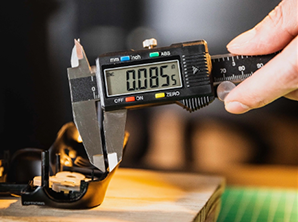
A measuring instrument’s display resolution is not the same as guaranteed measurement accuracy. When a result is close to a specification limit, measurement uncertainty and the acceptance rule can affect the conformity decision. ISO 14253-1 provides decision rules for verifying conformity or nonconformity while taking measurement uncertainty into account.
Inspection scope also affects price. First-article inspection, sampling, full inspection and a formal dimensional report require different time and documentation. Do not assume that CMM, FAI, material certificates or a complete report are automatically included with every laser-cut order. Define the requested evidence during quotation.
Three Buyer Examples
1. Cosmetic Stainless-Steel Cover
Use a suitable general tolerance for the non-critical outline. Individually control connector openings and mounting relationships. Identify the cosmetic face, protective-film instruction, acceptable edge condition and whether dimensions apply after deburring or finishing. Add flatness only where the cover must sit against a frame.
2. Automation Mounting Bracket
Reference the locating holes to functional datums. Ordinary bolt-clearance holes may not need the same control. If the bracket is bent, specify the final relationship between holes, faces and bend geometry—not only the flat-pattern dimensions. Identify any hole that requires drilling or reaming after cutting.
3. Acrylic Interlocking Panel
Define the real material grade and thickness, mating tab, fit intent and measurement face. Use a fit coupon before production when the assembly is sensitive. Inspect cosmetic edge clarity separately from slot width and overall dimensions.
Why Tighter Tolerances Increase Cost
A tighter tolerance can require a more stable material lot, slower or specially qualified processing, test coupons, alternative nesting, secondary machining, additional inspection, more detailed reporting and a larger rejection allowance. It may also reduce the supplier’s ability to substitute stock or combine the order efficiently with other work.
The goal is not to choose the loosest possible drawing. It is to assign tight control where failure would affect fit, alignment, sealing, safety or performance, while leaving cosmetic and non-functional geometry at an economical level. Our laser cutting cost guide and quotation guide explain how specification choices affect price.
Specifying Parts for Singapore Suppliers
For Singapore sourcing, provide metric dimensions, the exact material grade, delivery condition, thickness, drawing revision and required finished state. If a multinational customer specification or internal inspection standard applies, include it with the RFQ instead of assuming that every local supplier interprets a short note in the same way.
Identify whether the order is a prototype, pilot lot or repeat production. State whether future batches must use the same material manufacturer or whether approved alternatives are acceptable. For large, thin or cosmetic panels, add protective-film, separator, edge-protection and local-delivery requirements.
ISO 9001 certification describes a quality-management system; it does not by itself prove that a supplier can meet a particular laser-cut tolerance. Ask for process evidence, an approved sample or an inspection plan appropriate to the drawing. For broader supplier evaluation, see our Singapore sheet metal supplier guide and quality assurance overview.
A Practical Tolerance Review Workflow
Laser-Cutting RFQ Checklist
Include these items
- Part number and revision
- Material grade
- Approved alternatives
- Nominal thickness
- Quantity and annual volume
- DXF or STEP file
- Controlled PDF drawing
- General tolerance
- Individual critical tolerances
- Functional holes and slots
- Datums
- Measurement plane
- Edge-taper requirement
- Flatness requirement
- Burr and edge-break requirement
- Cosmetic face
- Protective-film instruction
- Cut-only or finished condition
- Bending, welding and finish
- Inspection method
- Inspection sample size
- FAI or dimensional report
- Material certificate or CoC
- Packaging requirement
- Singapore delivery address
- Required delivery date
- Substitution approval process
For guidance on minimum holes, slot width, edge distance, bend proximity and assembly features, use our sheet metal laser cutting design guide.
Frequently Asked Questions
What tolerance can laser cutting hold?
It depends on material, thickness, part size, feature geometry, edge condition, post-processing and inspection. Submit the drawing for review instead of applying one number to every part.
Is ±0.1 mm always achievable?
No universal value is guaranteed for every material, length, thickness and feature. A small profile, small hole, large panel and finished welded part require different capability reviews.
Is machine accuracy the same as part tolerance?
No. Motion-system accuracy excludes kerf, material response, taper, heat, edge condition and measurement uncertainty.
Does tolerance change with thickness?
Thickness influences energy, focus, kerf, taper and dross. The effect depends on material and feature geometry, so it must be evaluated with the actual drawing.
Are small holes less predictable than large profiles?
They can be. Piercing, local heat, taper and dross occupy a larger share of a small feature. Critical bores may need secondary machining.
How should laser-cut hole position be specified?
Reference functional holes to stable datums using an agreed coordinate or geometrical tolerance scheme. Avoid unnecessary chained dimensions.
Does kerf compensation guarantee tolerance?
No. It corrects the programmed path for measured material removal, but does not control flatness, taper, heat distortion, hole shape or inspection uncertainty.
Where should a tapered hole be measured?
The drawing should state whether size applies at the entry face, exit face or another plane. If taper matters, control it separately.
Is flatness included in laser-cutting tolerance?
No. Flatness is a separate characteristic affected by incoming sheet condition, stress release, geometry and handling.
When should a hole be drilled or reamed?
Use a secondary operation when the hole locates a component, carries a bearing or dowel, requires a precision fit, or needs controlled cylindricity and surface condition.
Does deburring change dimensions?
It can. Light removal of loose dross differs from grinding or edge rounding. Define the final inspection state and edge requirement.
Should ISO 2768 be placed on every drawing?
Only when the buyer and supplier understand the applicable edition, class and scope. Critical features still require individual specification.
What does ISO 9013 control?
It provides a classification framework for geometrical and quality characteristics of thermal cuts when referenced. It does not replace all dimensional, flatness or assembly requirements.
Do I need GD&T for a laser-cut part?
Not every simple part needs complex symbols. GD&T is useful when function depends on datum-related form, orientation, location or profile rather than isolated coordinate dimensions.
When is optical or CMM inspection required?
Use it when the characteristic, datum relationship or tolerance cannot be demonstrated reliably with simpler equipment. The method should be agreed before production.
What files should be sent for quotation?
Send a clean DXF for 2D geometry, STEP where formed or assembly context matters, and a controlled PDF for material, tolerances, datums, finish and inspection notes.
Why do tighter tolerances increase price?
They may require process trials, controlled stock, alternative cutting or machining, more inspection, formal reports and additional rejection allowance.
Should prototype and production tolerances be the same?
The functional requirement should remain consistent, but a prototype may use fit coupons or first-article approval before the production inspection plan is finalised.
Standards referenced
Need a Drawing and Tolerance Review?
Send the material, thickness, DXF or STEP, controlled PDF, quantity and critical characteristics. Lumen Future can review the cut geometry, process route and inspection requirements before quotation.