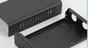
Quick answer: A perforated metal ventilation panel for equipment needs more than a repeat-hole drawing. Before fabrication, define the clear ventilation field, solid mounting borders, hole or slot pattern, mating frame, finished-state fit and how flatness will be checked. State the airflow or protection requirement separately: an open-area percentage describes geometry, not a verified cooling, filtration or safety result.
In this guide
For Singapore equipment builders, automation teams and maintenance buyers, a custom ventilation panel must fit an existing machine as well as present the intended opening pattern. A laser-cut sheet can match its DXF yet still interfere with a fan frame, sit unevenly on a cabinet, obscure a filter or leave too little solid material around fasteners. This guide is about specifying custom equipment ventilation panels as manufactured parts—not designing a complete HVAC system or certifying the finished machine.
Start With the Equipment Opening, Not the Hole Shape
Identify whether the required deliverable is a flat replacement cover, a removable cabinet side panel, or a formed panel that becomes part of an enclosure. Show where the panel meets the machine frame and what occupies the space behind it: a fan, filter, cable, bracket or service-access zone. Note which side faces the operator and whether the panel is routinely removed for maintenance.
The intended use changes what the drawing must control. A cover in front of a purchased fan needs the fan manufacturer’s mounting and clearance information. A service panel needs fastener access and repeatable orientation. A panel beside a seal or filter frame needs a defined mating surface. For broader enclosure coordination, see our control-panel and enclosure fabrication guide; the checks below concentrate on the individual vent panel.
| Panel situation | Information that prevents a fit problem | First-off check |
|---|---|---|
| Removable equipment cover | Mating opening, screw pattern, access direction, visible face and required clearance. | Installs and removes without forcing the panel or obstructing nearby hardware. |
| Fan or filter-facing panel | Component drawing, airflow direction, mounting zone and service space. | Approved assembly fits; customer verifies thermal or airflow performance separately. |
| Formed enclosure panel | Finished dimensions, bend direction, solid flange and alignment to the frame. | Post-form panel seats against the specified frame at the agreed check points. |
Map the Perforation Field and Keep-Out Areas
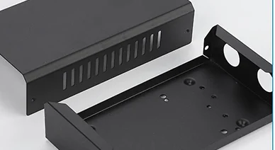
Mark the boundary of the perforated field, not only a repeated hole symbol. The drawing should state the hole or slot shape and size, pitch, row arrangement, pattern orientation and whether edge rows may be truncated. Also show the solid border around the field, fastener holes, bend or flange zones, labels, handles and any areas that must remain uncut. Dimension the pattern relative to functional datums, such as the equipment opening or mounting-hole centres, rather than relying on a visual centring instruction.
Keep fastener, bend and mating zones solid where the approved design requires them.
Do not assume that two patterns with similar visual density are interchangeable. A round-hole array, long slots and a staggered pattern remove material in different places, leave different ligaments and can interact differently with the panel edge. The applicable cut quality and practical spacing depend on material, thickness, feature count and the selected process. Our sheet-metal hole and slot design guide covers those general manufacturing considerations; this article uses them to coordinate a specific panel with its assembly.
Separate two area figures in the RFQ. “Open area within the perforated field” uses only that field as its denominator. “Net open area across the whole panel” includes solid borders and other uncut zones in the panel area. For a purely illustrative 300 × 200 mm panel with a 200 × 150 mm perforated field at 40% geometric open area, the nominal openings total 12,000 mm²: 40% of the field but only 20% of the whole panel. Neither percentage is a recommended design target or a measured airflow rate.
Do Not Treat Open Area as a Cooling Guarantee
Geometric free area can help the equipment designer compare pattern options, but it cannot by itself predict delivered airflow, temperature rise or pressure drop. The fan’s operating point, nearby obstacles, filter, flow direction and enclosure path all matter. The Industrial Perforators Association’s handbook discusses open area and pressure-loss testing under defined flow conditions, while Rittal’s industrial enclosure cooling paper explains how the installed fan, filter and cabinet affect usable airflow.
If cooling is a design requirement, the customer should supply the fan and filter details, airflow or heat-load target and any measured acceptance method. Lumen Future can review the requested panel geometry for fabrication; the equipment owner or appointed system specialist must verify the completed cooling design. A cut panel alone also does not establish dust protection, water ingress resistance or electrical-enclosure IP rating.
Define Flatness Where the Panel Has to Sit
Dense perforations remove stiffness and require many closely spaced cuts. On a wide or thin sheet, local heating, residual stress release and later handling may produce a wavy area or lifted corners. The risk cannot be reduced to one universal hole pitch or thickness rule. Perforated-sheet manufacturer Fahl notes that flatness is a specification to discuss, not an automatic property of a perforated part.
For a useful acceptance requirement, identify the surface or edge that must mate, the stage of manufacture and how the part is supported during measurement. “Flat after cutting on a bench” and “seats against the equipment frame after coating and fastening” are different conditions. If the installed panel may be pulled against a rigid frame, specify the permitted assembly gap or fastener effort; do not silently call a visibly bowed free-state part compliant just because screws can force it down.
A sample panel can reveal whether a changed border, pattern distribution, flange or production route is needed. Agree any change with the responsible designer because it can affect airflow geometry, appearance and fit. For measurement terminology and the wider causes of movement, see our sheet-metal flatness and inspection guide.
Give the Mounting Interface Its Own Dimensions
Provide the equipment opening dimensions, mating-frame drawing or photograph with scale, and the actual fastener positions. Mark the locating edge or datum, hole and slot orientation, screw-head clearance and whether access is from the front or rear. If a gasket, filter frame or fan guard is a separate purchased item, include its controlled drawing or part number and identify who supplies it.
Where a solid mounting border is required, dimension its minimum functional width from the approved design. A visually attractive row of holes that intrudes into a screw seat, bend line or sealing face may make the panel unusable. Conversely, making the border wider without approval can reduce the intended opening area. The first-off check should therefore use the real mating frame or a controlled fixture, not only a ruler laid across the cut sheet.
Safety and protection boundary: a perforated cover is not automatically an approved machine guard, EMI shield, filter or IP-rated enclosure. If the openings must prevent access to a hazard, resist water or dust, or provide electromagnetic shielding, the responsible equipment designer must specify and validate the complete system. An ordinary hole pattern is not equivalent to a shielded ventilation assembly or an enclosure assessed for an IP degree of protection under IEC 60529.
Confirm Material, Finish and the Manufacturing Route
State the metal grade, thickness, supplied surface condition and intended environment. An indoor control cabinet, a washdown area and an outdoor installation may need different corrosion and finish decisions. Do not substitute stainless steel grades, aluminium tempers or coatings based on the word “ventilation” alone. Where the panel has a visible face, mark the viewing side and any grain direction or appearance requirements; state the edge and burr condition needed for handling and assembly.
Custom laser-cut ventilation patterns can be useful for prototypes, non-standard outlines and design revisions. However, a very dense, uniform array can be time-consuming and may warrant comparing stock perforated sheet, punching or another route for a stable higher-volume design. This is a project-specific cost and feasibility decision—not a claim that Lumen Future operates every possible perforating process. Our laser-cutting versus stamping guide explains the volume trade-off.
Indicate whether the purchased item is a flat cut panel or includes bending, welding, deburring, coating or other finishing. Confirm the agreed process and inspection state in the quotation. Protect thin or cosmetic panels during stacking and delivery so a satisfactory first-off does not arrive scratched or bent.
Approve One Panel Before Repeating a Risky Pattern
For a new or demanding pattern, agree whether a first-off sample is needed. A useful review checks the physical part against the approved drawing and then, where practicable, against the actual equipment interface. Record the drawing revision and any agreed changes before repeat production.
| Check | What to agree before production | Who confirms the result |
|---|---|---|
| Pattern and appearance | Hole or slot geometry, field boundary, orientation, visible face and permitted edge condition. | Fabricator against the approved drawing; customer approves any change in visual or functional intent. |
| Dimensions and fit | Critical mounting datums, hole positions, mating gap and the measurement state: cut, formed or finished. | Fabricator checks specified dimensions; customer confirms the part fits the intended assembly. |
| Flatness | Free-state support and/or installed-state frame, check locations and allowable result. | As stated in the order; do not substitute one state for the other. |
| Airflow or protective performance | System test method, if needed, including fan, filter, operating condition and acceptance target. | Equipment owner or appointed specialist; not inferred from geometric open area. |
RFQ Checklist for Singapore Equipment Projects
For a quotation on laser cut ventilation panels in Singapore, send a coherent package rather than a pattern image alone:
- Drawing set: 1:1 DXF for the cut profile, dimensioned PDF with revision and datums, and STEP if bends or assembly relationships matter.
- Panel and pattern: overall size, material grade and thickness, hole or slot details, pitch, field boundary, solid borders and prohibited cut zones.
- Interface: equipment opening, mating frame, fastener and fan/filter references, viewing side and front/rear installation direction.
- Delivered state: flat or formed, finish and deburring scope, cosmetic face, packing and part identification.
- Acceptance: critical dimensions, free or installed flatness condition, first-off fit check, required records and the person authorised to approve a revision.
- Order: prototype and repeat quantities, required date and Singapore delivery location.
If you have an existing panel but no complete CAD, provide clear photographs, several verified dimensions and the physical sample if available. An old part may have wear or deformation; any recreated drawing and changed requirements still need customer approval before production.
Frequently Asked Questions
Does a 40% open-area pattern guarantee sufficient ventilation?
No. It states a geometric ratio for a defined area, not the airflow through an installed fan, filter and enclosure. The equipment designer should validate the complete operating system.
Should flatness be checked before or after mounting?
Specify the condition that matters to the order. If free-state appearance and installed fit both matter, define both and identify the inspection stage, support and permitted assembly gap.
Is laser cutting always the best method for a dense hole pattern?
No. Custom geometry and revisions may suit laser cutting, while a large, uniform array or high repeat volume may favour another production route. Compare feasibility, flatness, quantity and total cost for the actual drawing.
Can a perforated panel be called a safety guard or IP-rated cover?
Not on the basis of hole cutting alone. Hazard access, ingress protection and any other system-level rating require the equipment owner’s design and validation.
Request a Ventilation Panel Fabrication Review
Send the approved panel drawing, pattern map, mating-frame details, material, quantity and required finish. Mark where the panel must sit flat and which holes or borders control installation. Lumen Future can review the requested sheet-metal cutting and downstream fabrication scope before quotation; airflow, thermal and protective performance remain separate equipment-level requirements.
Review sheet-metal cutting capabilities · Send your drawing and enquiry →