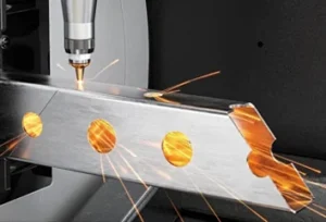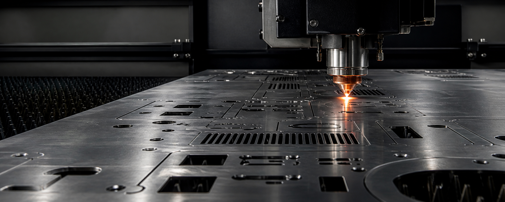
Use thickness-based rules only as preliminary checks, then confirm the geometry against the actual laser process, bending tools, tolerance, finish and assembly requirements.
A flat part can look simple while containing several manufacturing risks: a small hole that cannot hold its intended fit, a narrow slot with trapped scrap, a weak web near the edge, or a fastener hole that distorts during bending. These issues are easier and less expensive to resolve before quotation.
This sheet metal laser cutting design guide brings holes, slots, edge distance, bend clearance, tabs, notches and reliefs into one DFM workflow. It is written for engineers and procurement teams preparing custom sheet-metal parts in Singapore. For a drawing review, see our sheet metal laser cutting service.
Quick Sheet-Metal Design Checklist
Published rules from different manufacturers vary because their equipment, materials, tooling and acceptance criteria differ. Xometry and Protolabs, for example, publish different combinations of thickness-based and fixed minimum dimensions. Treat these as supplier-specific guidelines rather than universal laser-cutting standards.
Kerf and Nominal Dimensions
Kerf is the width of material removed by the laser. It changes with material, thickness, laser system, focus, assist gas and cutting parameters. Internal and external contours need compensation in opposite directions if the finished nominal size is to be maintained.
Who should apply kerf compensation?
In a normal digital workflow, the designer supplies the required nominal geometry and the fabricator applies process compensation in CAM. Manually enlarging every hole or shrinking every outside profile can create double compensation if the supplier also offsets the cutting path.
- Draw the required finished profile unless instructed otherwise.
- Do not mix a kerf-compensated DXF with an uncompensated STEP model without explanation.
- If compensation is already built into the file, identify it clearly in the drawing and RFQ.
- Do not assume one kerf value for different materials and thicknesses.
- Remember that deburring, coating and plating may also affect the final fit.
Minimum Hole Size for Laser-Cut Sheet Metal
There is no universal minimum hole diameter. A hole that can be cut is not automatically suitable for its functional purpose. Feasibility and quality depend on:
- Material and alloy grade.
- Nominal and actual sheet thickness.
- Hole diameter and shape.
- Piercing method and local heat input.
- Number and spacing of holes.
- Required edge condition and tolerance.
- Whether the part will later be bent, welded, coated or machined.
| Hole function | Laser-cut condition may be suitable for | Additional review |
|---|---|---|
| General clearance hole | Bolts, screws and access | Allow practical assembly clearance |
| Ventilation hole | Airflow and perforated patterns | Review heat accumulation, pitch and panel stiffness |
| Dowel or locating hole | Near-net pre-hole | Drilling or reaming may establish final fit |
| Bearing bore | Initial material removal | Consider boring, reaming or CNC machining |
| Thread pilot | Pre-cut opening where reviewed | Confirm tap-drill size, engagement and post-cut operation |
| Cosmetic hole array | Decorative or ventilation pattern | Review surface protection and thermal distribution |
A diameter-to-thickness ratio can be an early screening tool, but it should not be copied into every drawing as a guaranteed limit. Mark the function and required fit so the supplier can confirm whether laser cutting is the final process or only the first operation.
Minimum Slot Width and Cut-Out Design
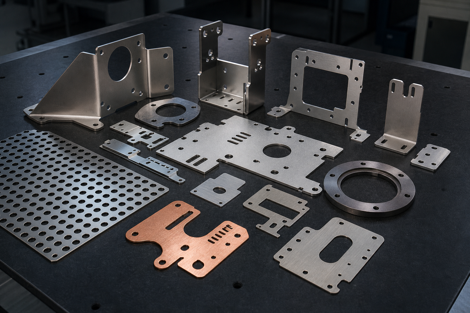
Slot design involves more than width. Review the slot length, end geometry, piercing location, adjacent material and whether the internal slug can release safely.
- Width: narrow slots can concentrate heat and may not produce the required edge condition.
- Length: a long opening can reduce local panel stiffness.
- End shape: the mating tab must seat without interfering with the slot radius or cut condition.
- Piercing: the process needs a suitable place to initiate the cut.
- Slug release: small or unstable cut-outs may remain attached or interfere with processing.
- Spacing: a narrow bridge between the slot and another feature can move or overheat.
Some public design guides suggest enlarged “lollipop” ends for selected slot geometries. Do not add them automatically: they change the finished part and may not be needed for the selected laser strategy. Add pierce-relief geometry only after supplier review.
Hole-to-Edge and Hole-to-Hole Distance
Define what “edge distance” means
Edge distance may be reported from the hole centre to the part edge or from the nearest hole edge to the part edge. Mixing these definitions creates avoidable mistakes. For DFM discussion, a useful value is:
Hole-to-part-edge risks
Too little remaining material can cause:
- Local distortion during cutting or deburring.
- Weakness during handling and assembly.
- Heat concentration near the outside profile.
- Fastener pull-out or bearing concerns.
- Visible edge inconsistency on cosmetic parts.
A manufacturable edge distance is not proof that a loaded connection is structurally adequate. The customer’s engineer must verify bearing, tear-out and other connection requirements.
Hole-to-hole risks
Evaluate the material bridge between adjacent cut edges, not only the centre-to-centre pitch. Dense patterns can accumulate heat and reduce sheet stiffness. For perforated panels, consider the open-area percentage, surrounding border, cutting sequence, pattern symmetry and whether punching may be more economical at stable high volumes.
Hole and Slot Distance from a Bend
Bending stretches material on the outside of the bend and compresses it on the inside. Holes, slots and cut-outs within the deformation zone may become oval, shift, pull toward the bend or prevent the tooling from supporting the flange correctly.
Why the common 4T rule is only a first check
A distance based on four times material thickness is widely published as a practical early warning. It does not include every variable. Actual feature clearance also depends on:
- Inside bend radius.
- Material grade and temper.
- Thickness and grain direction.
- Press-brake tooling and die opening.
- Bend angle and forming method.
- Hole size, slot length and feature orientation.
Protolabs publishes both a general 4T convention and more detailed material-, thickness- and radius-dependent guidance. This illustrates why the final distance must follow the actual bending process rather than a universal number.
Measure from a meaningful bend reference
“Distance to bend line” is ambiguous unless the bend line is defined. Agree whether the requirement is measured from the feature edge to the bend tangent, bend zone or another controlled reference. The drawing should describe the finished functional dimension, not merely a decorative line in the DXF.
When a feature must be close to a bend
- Move the hole or slot outside the deformation region.
- Change the flange or bend radius.
- Add a suitable relief around the feature.
- Accept controlled deformation if function permits.
- Drill or machine the feature after bending.
- Split the part into simpler components and join them later.
For bend allowance, K-factor, radius and springback, use our CNC bending tolerance and K-factor guide.
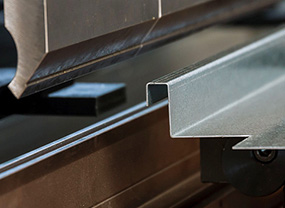
Tabs, Slots, Notches and Corner Relief
Tabs and slots for assembly
Tabs and slots can help orient parts, prevent reversed assembly, reduce manual marking and support fit-up before welding. They do not automatically eliminate fixtures, tolerance variation or welding distortion.
| Design intent | Feature approach | DFM question |
|---|---|---|
| Hand assembly | Free or controlled slip fit | What clearance remains after deburring and finishing? |
| Weld location | Tab and slot with access around the joint | Does the geometry support the welding sequence? |
| Error-proof orientation | Asymmetric tab pattern | Can the part engage in any incorrect direction? |
| Insertion-depth control | Shoulder, stop tab or keyed feature | Which surface establishes the functional position? |
| Final mechanical fit | Process-specific controlled interface | Is laser cutting sufficient, or is machining required? |
Do not apply one fixed tab-to-slot clearance to stainless steel, aluminium, coated steel and every thickness. State whether the part should slide freely, assemble by hand, retain lightly or only locate before welding. The fabricator can then determine appropriate compensation.
Notches
Review notch width, depth, root geometry, adjacent material and the direction of load. Deep narrow notches and long thin tabs can distort or create unnecessary stress concentration. Make sure the removed slug can separate and that the remaining feature can survive handling.
Bend and corner relief
Reliefs help material move where two flanges, bends or corners meet. Their geometry should reflect material thickness, bend radius, flange length, welding and appearance requirements. An undersized relief can contribute to tearing or bulging; an oversized relief may leave an unacceptable opening.
Why Tight-Fit Holes Often Need Secondary Machining
Laser cutting is highly effective for profile creation, but it should not automatically be treated as the finishing process for every precision interface.
| Feature | Direct laser cutting may suit | Consider secondary processing for |
|---|---|---|
| Clearance hole | General bolts and access | Very controlled fit or geometry |
| Dowel hole | Near-net pilot | Drilling and reaming to final size |
| Bearing bore | Initial material removal | Boring or CNC machining |
| Threaded hole | Reviewed pilot geometry | Drilling, tapping or thread forming |
| Post-weld feature | Pre-location or access | Machining after welding when final position is critical |
A practical route is to laser-cut most of the geometry, then drill, bore, ream or machine only the characteristics that require precision fit, controlled surface condition or post-weld location.
DXF, STEP and PDF File Requirements
| File | Primary purpose | Key check |
|---|---|---|
| DXF | Final 2D cutting profile | 1:1 scale, correct units, closed contours and no duplicate lines |
| STEP | Folded geometry, assembly interfaces and 3D design intent | Use the same revision as the cutting file and drawing |
| Material, thickness, datums, tolerances, finish and inspection | Do not rely on an unscaled screenshot |
- Do not leave dimensions, centre lines or notes in the cutting layer.
- Do not allow bend lines to be interpreted as cut lines.
- State whether an unfolded DXF includes bend allowance or supplier-specific compensation.
- Avoid conflicting flat patterns generated from different K-factors.
- Identify cosmetic face, grain direction and protective-film requirements.
For general file problems, see our CAD file preparation guide. For format selection, read STEP vs IGES vs DXF.
Review DFM by Material and Thickness
| Material family | DFM review priorities |
|---|---|
| Stainless steel | Heat distribution, edge condition, cosmetic face, deburring and downstream welding |
| Mild and carbon steel | Thickness, scale or coating condition, structural use and finishing route |
| Aluminium | Alloy, temper, surface protection, heat response and local stiffness |
| Brass | Reflectivity, surface appearance, thickness and feature density |
| Copper | Reflectivity, thermal conductivity, thickness, hole pattern and equipment capability |
| Galvanised sheet | Coating condition, cut edge, welding and downstream corrosion protection |
DFM rules should be reviewed against the exact grade and thickness—not only the material family. If the design begins with gauge rather than millimetres, use our sheet metal gauge and thickness guide. For dimensional requirements, see Laser Cutting Tolerances in Singapore.
Copyable Pre-Submission Checklist
- Material, grade and thickness are specified.
- Prototype and production quantities are provided.
- DXF is 1:1 with correct units and closed contours.
- Duplicate lines and non-cutting geometry are removed.
- STEP, DXF and PDF use the same revision.
- Hole and slot functions are identified.
- No unconfirmed manual kerf compensation is included.
- Remaining material to edges and adjacent features has been reviewed.
- Features near bends have been checked against the intended tooling and radius.
- Tab-and-slot assembly condition is defined.
- Required bend and corner reliefs are shown.
- Precision holes requiring machining are identified.
- Cosmetic face, grain direction and protective film are specified.
- Deburring, bending, welding, finishing and inspection are stated.
- Delivery location and required schedule in Singapore are included.
Frequently Asked Questions
What is the minimum hole size for laser-cut sheet metal?
There is no universal minimum diameter. It depends on material, grade, thickness, piercing conditions, feature position, hole density and required edge quality. Use thickness-based rules only as preliminary DFM checks and confirm the actual feature.
How close can a hole be to a sheet-metal edge?
Evaluate the remaining material from the nearest hole edge to the part edge. Practical spacing depends on thickness, hole size, material, load, cutting conditions and finishing. Structural tear-out or bearing requirements must be verified separately by the design engineer.
How wide should a laser-cut slot be?
Slot feasibility depends on material, thickness, length, end geometry, piercing strategy and required fit. Do not use one slot-width-to-thickness formula for every material and supplier.
How far should a hole be from a bend?
A four-times-thickness rule is a useful early warning, not a universal guarantee. Final clearance depends on bend radius, material, thickness, tooling, angle, feature size and how the distance is referenced.
How much clearance should tabs and slots have?
Clearance depends on the intended assembly fit, material, thickness, kerf compensation, deburring, coating and welding requirements. State whether the parts need a free slip fit, hand assembly or welding location, then confirm the compensation with the fabricator.
Should precision holes be laser cut or machined?
Laser cutting can efficiently create a near-net hole. Dowel, bearing, precision-fit, threaded or post-weld critical holes may require drilling, boring, reaming, tapping or CNC machining for the final requirement.
Should I send DXF, STEP or PDF files?
Use DXF for the final 2D cutting profile, STEP for folded geometry and assembly intent, and PDF for material, thickness, datums, tolerances, finish and inspection requirements. Keep all files on the same revision.
Sources and Technical Context
- Xometry: sheet-cutting feature and spacing guidelines
- Xometry: laser and sheet-cutting design guide
- Protolabs: sheet-metal fabrication design guidelines
- Protolabs: material-, thickness- and bend-dependent DFM guidance
- OSH Cut: bend zones, flange support and sheet-metal terminology
Send Your Sheet-Metal Design for DFM Review
Share the DXF, STEP model, PDF drawing, material, thickness and quantities. Lumen Future can review holes, slots, edge distances, bend areas, secondary operations and inspection requirements before quotation.