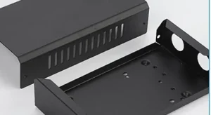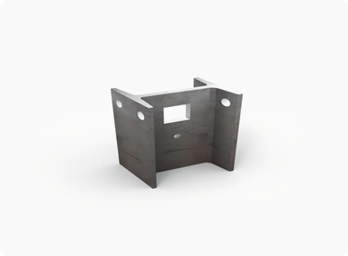
This anonymised Singapore project workflow shows how a laser-cut and bent sheet metal bracket can move from released design files to a physical prototype for assembly evaluation. The rapid route came from a complete file package, prompt DFM decisions, confirmed material, coordinated cutting and bending, and a defined inspection scope—not from skipping engineering review.
For an equipment engineer, a prototype is not simply a smaller production order. It is a controlled way to answer questions: Does the bracket fit the assembly? Are the holes accessible? Is the flange orientation correct? Can the part be manufactured repeatedly without unnecessary cost?
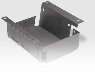
This case focuses on a local industrial equipment bracket requiring a flat laser-cut profile, deburred edges, CNC-formed flanges and dimensional checks before customer assembly evaluation. It complements our general DXF-to-delivered-parts workflow by showing how decisions are compressed when the objective is a rapid prototype rather than a full production release.
Representative Project Brief
| Project item | Anonymised case scope | What a real RFQ must state |
|---|---|---|
| Application | Industrial equipment mounting or support bracket | Assembly function, load direction and mating components |
| Part type | Laser-cut flat blank with formed flanges | Part number, revision and released geometry |
| Material | Project-approved sheet metal | Grade or alloy, temper where relevant, and nominal thickness |
| Prototype objective | Fit, access and manufacturing evaluation | Questions the prototype must answer |
| Processes | Drawing review, laser cutting, deburring, CNC bending and inspection | Any welding, inserts, marking, coating or packaging |
| Critical features | Selected holes, flange relationships and overall formed envelope | Datums, tolerances and measurement method |
| Schedule | Rapid project-specific slot after file and material confirmation | Required date, approval response time and delivery location |
| Result | Prototype prepared for customer assembly evaluation | Fit-test feedback and changes required before repeat production |
The omitted values are not marketing gaps to fill with estimates. For a production case record, each should be replaced only with data released from the real order.
The Engineering Challenge
The project needed to turn digital geometry into a physical part quickly enough for the engineering team to continue an equipment build. At the same time, the prototype still needed a controlled revision, unambiguous bends and measurable assembly interfaces.
Three risks mattered more than raw machine speed:
- File interpretation: the flat cutting geometry, formed model and drawing had to describe the same revision.
- Bend-dependent features: holes and flange dimensions could not be evaluated as if the component remained flat.
- Inspection priorities: critical assembly features needed attention without applying the tightest tolerance to every edge.
Files Received and Reviewed
A useful sheet metal prototype package separates machine geometry from engineering intent. For this type of project, the review uses:
- a supplier-approved 2D file for the intended cut profile;
- a STEP model or other suitable 3D reference for the formed part;
- a dimensioned PDF identifying material, thickness, bends and critical dimensions;
- part number and matching revision across all files;
- prototype quantity, required date and Singapore delivery or collection requirement.
A DXF alone may define the flat outline but not the final bend direction, formed envelope, tolerances or inspection datums. Our CAD file preparation guide explains how to separate production geometry, drawing information and RFQ details.
DFM Review Before Cutting
The team reviewed the bracket as a formed component rather than treating it as an isolated flat profile. The applicable checks included:
- material and nominal thickness were defined consistently;
- bend directions and the intended finished orientation were unambiguous;
- holes and slots near bends could be reviewed for deformation risk;
- inside bend radii and relief geometry suited the proposed forming route;
- critical dimensions were identified separately from general geometry;
- cosmetic faces and acceptable edge condition were understood;
- the flat pattern would be generated or approved through the agreed workflow.
Not every project needs a redesign. The purpose of DFM is to identify decisions before material is cut, document any agreed change and keep the customer-controlled model and drawing aligned. For formed-part behaviour, see our guide to K-factor, bend allowance and springback.

Rapid Prototype Manufacturing Route
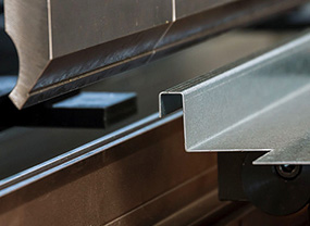
Laser cutting supports rapid iteration because a changed profile can normally be programmed from updated digital geometry without a dedicated cutting die. The bending operation still requires tooling access, a feasible radius and a controlled sequence. Lumen Future coordinates metal laser cutting with CNC bending and folding for suitable prototype parts.
What “Rapid” Means in This Case
The rapid schedule was project-specific and began only after the applicable files, material and manufacturing scope were confirmed. It does not create a standing lead-time promise for every sheet metal prototype.
| Schedule factor | How it supported the project | What could delay another order |
|---|---|---|
| File readiness | Matching files reduced interpretation and rework | Conflicting revisions, open contours or missing bend intent |
| Material | Confirmed material allowed planning to proceed | Special alloy, finish, certificate or unavailable thickness |
| DFM response | Engineering questions could be closed before cutting | Unresolved tolerance or design decisions |
| Process scope | Cutting, deburring and bending were coordinated | Welding, coating, inserts or outsourced finishing |
| Inspection | Critical features were prioritised | Unspecified reports, fixtures or third-party inspection |
| Local handover | Singapore delivery or collection could be planned directly | Site-access limits, late transport changes or public holidays |
A short machine cycle does not guarantee a short delivered lead time. Quotation clarification, material procurement, customer approval, secondary processes, inspection and transport all sit on the same critical path.
Inspection for an Assembly Prototype
The inspection plan should answer the prototype objective. For a formed mounting bracket, relevant checks may include:
- material and thickness against the released requirement;
- overall flat profile and selected hole or slot locations;
- flange direction, angle and formed height;
- relationship between mounting features after bending;
- edge condition and designated cosmetic surfaces;
- physical fit against the intended mating parts, where included in scope.
A blanket tolerance should not be inferred from a service-page headline. Material condition, geometry, bend sequence, tooling and measurement setup affect the result. Critical requirements belong on the drawing and should be reviewed before quotation; our laser cutting tolerance guide explains how to specify them.
Outcome and Next Decision
This page does not claim that the design entered production unchanged. Finding a needed revision can be a successful prototype outcome when it prevents a larger batch from being built incorrectly.
Lessons for Singapore Engineering Teams
- Define what the prototype must prove. Fit, appearance, stiffness and process validation are different objectives.
- Send the formed model and drawing. A flat DXF rarely communicates the complete part.
- Prioritise critical dimensions. Tightening every dimension can add cost and delay without improving the assembly test.
- Separate prototype speed from production approval. A successful first part does not replace repeat-process qualification.
- Plan local review. Same-time-zone questions, collection and physical fit checks can help the next design decision happen sooner.
Teams sourcing automation components can also review our guide to laser cutting for industrial automation parts. Buyers comparing suppliers should use the broader Singapore sheet metal fabrication supplier guide.
Rapid prototype RFQ checklist
- Part number and revision
- Prototype objective
- Material grade or alloy
- Nominal thickness in mm
- Quantity
- 2D production file
- STEP model
- Dimensioned PDF
- Bend direction and radius
- Critical dimensions
- Deburring requirement
- Cosmetic faces
- Welding or inserts
- Surface finish
- Inspection evidence
- Required date and location
If a legacy drawing uses gauge rather than millimetres, check the material-specific conversion in our sheet metal gauge chart. Include the required material and controlling nominal thickness rather than sending a gauge number alone.
Frequently Asked Questions
How quickly can a laser-cut sheet metal prototype be produced in Singapore?
Lead time depends on file readiness, material availability, quantity, bending or welding, finishing, inspection and current capacity. Ask for a project-specific confirmed date after the complete RFQ is reviewed.
What files are needed for a sheet metal prototype?
A supplier-approved 2D cutting file is commonly useful for the flat profile. Bent parts should also include a 3D model and dimensioned drawing with material, thickness, bends, critical tolerances and finish.
Can one prototype be laser cut without dedicated tooling?
The cutting profile normally does not require a part-specific die. Bending still uses press-brake tooling and must suit the material, thickness, radius and geometry.
Should the first prototype include the final surface finish?
Only when finish is part of the validation objective. A fit-only prototype may omit coating to save time, while a cosmetic or corrosion test may require the complete finish. Record any difference from production intent.
What tolerances should be specified?
Identify the dimensions that affect fit, alignment, function and downstream assembly. Do not apply an unnecessarily tight blanket tolerance without checking process feasibility and measurement method.
Does a successful prototype mean the design is ready for production?
Not automatically. The prototype may confirm geometry and fit, but repeatability, production inspection, finishing, packaging and change control still need review before batch release.
Can project details remain confidential?
Yes. State the confidentiality requirement before sending files. Public case material should use only information and images approved for disclosure.
Request a Sheet Metal Prototype Review
Send the released files, material, thickness, quantity, critical dimensions and required date. We can identify open manufacturing questions and confirm an appropriate project scope and schedule.