Sheet metal nesting affects how much purchased material is allocated to each laser-cut part. It can also change cutting distance, pierce count, unloading effort and the practical value of the remaining sheet. The best production nest therefore balances material yield with cut quality, thermal stability, traceability and downstream work—not utilization alone.
Quick answer
Nesting is the arrangement of one or more part geometries on a sheet before laser cutting. An efficient nest can reduce unused sheet area and lower the material component of part cost. However, the tightest geometric arrangement is not automatically the lowest-cost or safest production plan. Part spacing, lead-ins, heat distribution, grain direction, cosmetic surfaces, tipped parts, sorting and inspection requirements all influence the final CAM program.
This guide focuses on nesting and material utilization. For the wider quotation picture—including material grade, thickness, setup, assist gas, cutting time and finishing—see our laser cutting cost guide for Singapore buyers.
What Is Sheet Metal Nesting?
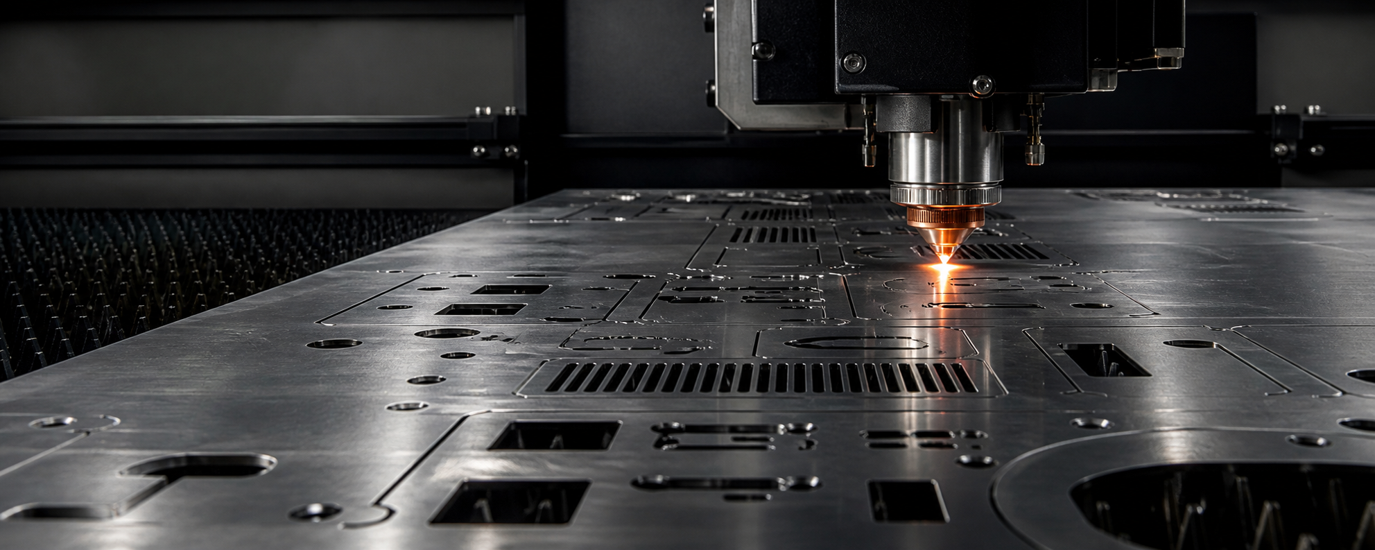
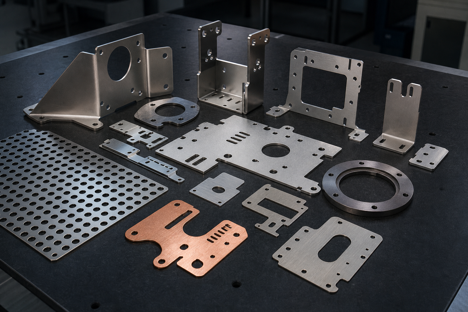
In laser cutting, a nest is the production layout that places component profiles on a selected sheet. Nesting software imports part geometry, applies manufacturing rules and creates the toolpaths used by the laser. A production nest therefore contains more information than a visual puzzle of shapes.
Before cutting, the programmer may need to define lead-ins and lead-outs, cut direction, contour priority, kerf compensation, micro-joints, part spacing, head movement and skeleton cut-up. The layout must also leave the sheet and individual parts sufficiently stable during processing. Small profiles that tip into the cutting path, heat concentrated in one area or a weak remaining skeleton can turn a visually dense nest into an unreliable one.
Why Material Utilization Affects a Laser-Cutting Quotation
Raw sheet cost is allocated across the usable parts produced from a sheet. If a job needs more sheets because part shapes leave unusable gaps, its material allocation per part normally increases. The relationship is easiest to understand as a model:
This is not a complete quotation formula. A real price may also include programming, setup, cutting time, pierces, assist gas, consumables, unloading, deburring, bending, welding, finishing, inspection, packaging and delivery. Material certificates, cosmetic sheet requirements and minimum purchase quantities can also affect the relevant sheet cost.
A higher utilization percentage may reduce material allocation while increasing programming or handling effort. For example, filling every small gap with unrelated components may look efficient but create extra sorting and traceability work. Similarly, an irregular offcut may count as remaining area without being economical to store or reuse.
What Controls Sheet Metal Nesting Efficiency?
| Factor | Effect on the nest | Possible cost or quality consequence |
|---|---|---|
| Part geometry | Curved or irregular outlines may leave areas that other parts cannot fill. | More sheet area may be allocated to each component. |
| Quantity | Larger quantities give the software more repeated shapes and combinations. | Yield may improve, but production and inventory needs still matter. |
| Available sheet sizes | The same parts may fit differently on different standard formats. | Purchasing MOQ, stock availability and machine capacity affect the practical choice. |
| Part rotation | Rotation can fit shapes into unused pockets. | Grain, brushed finish, bend direction or assembly orientation may prohibit rotation. |
| Part spacing | Closer profiles reduce the web of material between components. | Excessive closeness can compromise stability, lead placement or edge quality. |
| Mixed-part nesting | Smaller parts may fill gaps around larger ones. | Sorting, revision control and order traceability become more demanding. |
| Internal features | Some software and processes may allow suitable parts within large cutouts. | Stability, cut order and quality must be validated before using the opportunity. |
| Remnant inventory | Known remnants provide additional sheet-size options. | Useful only when grade, thickness, condition and traceability remain controlled. |
Part design affects nesting before the CAM software starts. Long projections, unnecessary decorative contours and very narrow webs may restrict rotation or create fragile scrap. If cost is important, review functional geometry using the sheet metal laser cutting design guide, but do not alter critical load paths or assembly requirements merely to improve sheet utilization.
Part Spacing, Kerf Compensation and Lead-Ins
Three terms are often confused:
- Kerf is the width of material removed by the cutting process.
- Kerf compensation offsets the programmed toolpath so the finished contour approaches the nominal geometry.
- Part spacing is the planned distance between neighbouring component profiles in the nest.
Unless instructed otherwise, the buyer should send nominal finished geometry. The fabricator applies process-specific offsets in CAM. Manually adding kerf to a customer DXF can create double compensation and dimensional error.
Part spacing is not simply equal to kerf width. The programmer may need room for lead-ins, pierces, heat dissipation, micro-joints and a stable skeleton. Hole slugs or small parts can tip upward, so the cut order and head travel path must also be considered. The required spacing changes with material, thickness, geometry, process settings, sheet support and the required edge condition.
When Does Common-Line Cutting Work?
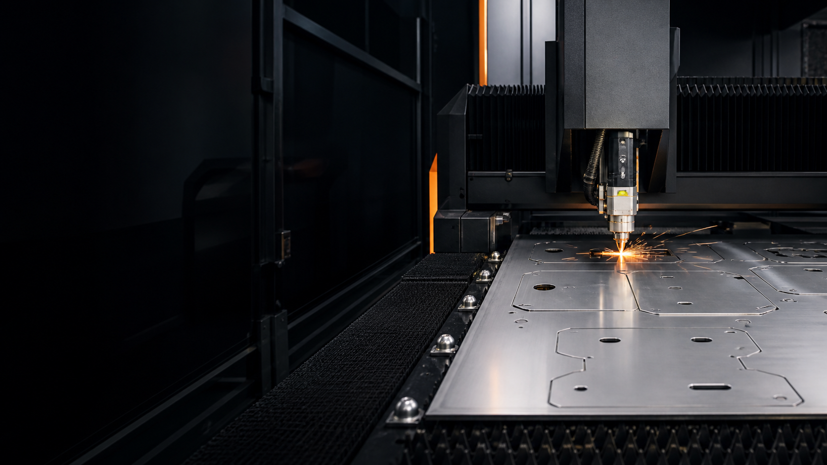
Common-line cutting allows two adjacent components to share one programmed cut edge instead of using two parallel paths. For suitable geometry, it can eliminate the normal separation between those edges, reduce cutting distance and sometimes reduce the number of pierces.
It is most straightforward for compatible straight-edged parts arranged in a controlled array. It is not an automatic choice for every pair of straight edges. The CAM strategy must still account for kerf compensation, cut sequence, heat movement, part release, edge requirements and repeatability.
| Common-line may be considered when | Separate contours may be safer when |
|---|---|
| Adjacent edges are geometrically compatible. | The two edges have different quality or dimensional requirements. |
| Part movement and thermal effects can be controlled. | Releasing one component could move or destabilize the other. |
| The cutting sequence preserves sheet and part support. | Critical cosmetic or assembly edges need independent control. |
| The process allows correct compensation on the shared path. | Micro-joints, lead positions or downstream handling conflict with the shared edge. |
CAM suppliers describe common-line cutting as a method for sharing a cut path, reducing separation scrap and potentially decreasing pierces and cutting distance. Those are production opportunities, not universal guarantees; the fabricator still validates the actual nest and process.
Grain Direction, Protective Film and Cosmetic Surfaces
Free rotation usually gives nesting software more options. Real parts are not always direction-free.
Grain and bend direction
Material direction may matter for formed components or engineered properties. If the drawing controls the relationship between rolling direction and a bend or feature, the nest must preserve it. The customer’s engineer should define the necessary orientation; the fabricator should not infer a structural requirement from the 2D outline.
Brushed and directional finishes
Hairline, brushed and patterned sheets often require visible faces to run in a consistent direction. Rotating a component by 90 degrees may improve geometric yield while producing a visibly mismatched assembly. The PDF should identify the visible face and finish direction.
Protective film and scratch control
Film suitability depends on the film, substrate and laser process. Cosmetic parts may also need controlled unloading, stacking and interleaving. A dense mixed nest that increases contact or sorting risk may be a false economy if parts require rework or replacement.
Can Remnants Be Reused?
A remnant can be useful when its identity and physical condition remain suitable for the next job. A practical remnant system records material grade, thickness, dimensions, surface condition and location. Certificate or heat-traceability requirements may further limit reuse.
Before assigning a remnant, the fabricator may need to confirm:
- the material grade and thickness are known;
- the remaining shape is large enough for clamping, support and safe cutting;
- the sheet is sufficiently flat and free from unacceptable corrosion or contamination;
- surface finish, film and cosmetic requirements match the new job;
- batch, certificate and customer segregation requirements can be maintained; and
- the expected saving is greater than the retrieval, inspection and programming effort.
An irregular offcut may contain considerable physical area but little practical nesting value. Conversely, a well-recorded rectangular remnant can be useful for prototypes, replacement pieces or small batches.
Single-part, mixed-part and multi-order nests
| Strategy | Potential advantage | Control needed |
|---|---|---|
| Single-part nest | Simple counting, repeatability and sorting. | Irregular parts may leave large unused pockets. |
| Mixed-part nest | Large and small geometries can complement each other. | Common material, thickness, finish and process requirements must be verified. |
| Multi-order nest | Can improve yield across compatible customer jobs. | Revision, certification, due date, segregation and traceability controls are essential. |
| Remnant nest | May avoid opening a new full sheet for a small quantity. | Inventory accuracy, flatness, usable boundary and setup effort must be considered. |
For purchasing, combining parts made from the same confirmed grade and thickness can create more nesting options. However, do not combine requirements casually: a nominally similar material may have different certificates, finishes, grain constraints or quality plans.
Illustrative Nesting and Material Allocation Example
Layout B allocated area: 2.50 ÷ 44 = 0.0568 m² per part
This example demonstrates allocated sheet area only. It does not prove that Layout B has the lower total price. The revised nest could change programming, cutting distance, pierce count, heat distribution, unloading, identification or inspection. A proper comparison reviews accepted parts and total production cost—not just bounding-box area or a single utilization percentage.
Utilization metrics should also be defined consistently. Software may report true part area, rectangular utilization or another measure. If two quotations appear to use different material assumptions, review the complete scope using our guide to reading a laser cutting quotation.
How Buyers Can Reduce Cost Without Sacrificing Quality
- Provide realistic quantities. Prototype, batch and annual demand help the fabricator evaluate purchasing and nesting options.
- Group compatible parts. Submit parts with the same confirmed grade, thickness and finish together, while keeping revision control clear.
- Allow standard sheet evaluation. Do not prescribe a sheet size unless the project genuinely requires it.
- Identify only necessary direction constraints. Clearly mark grain, brushed finish and visible faces without restricting rotation where it has no functional value.
- Distinguish precision features. Dowel, bearing, threaded and close-fit holes may need secondary machining; state this on the drawing.
- Review non-functional complexity. Decorative edges and unnecessary projections can increase cutting and reduce nesting flexibility.
- Keep nominal CAD geometry. Let the fabricator apply machine-specific kerf compensation and production spacing.
- Provide consistent files. Use DXF for 2D profiles, STEP for formed or assembly intent and PDF for controlled requirements. See our STEP, IGES and DXF guide.
- Allow DFM feedback. A small non-functional geometry change may create a better repeat arrangement, but any revision should be approved before production.
If you are preparing cutting files, use the CAD file preparation checklist. For material thickness conversions, consult the sheet metal gauge chart.
RFQ Checklist for a Nesting-Aware Quotation
The information lets the supplier evaluate material selection, standard sheet formats, part orientation, mixed-nest compatibility and downstream handling. It does not require the buyer to create the final production nest.
Frequently Asked Questions
What is nesting in sheet metal laser cutting?
Nesting is the CAM planning process that arranges one or more part geometries on a sheet and prepares a viable cutting program. It considers material usage together with process spacing, lead-ins, cut sequence, part stability and machine movement.
How does nesting affect laser-cut part cost?
It influences how much purchased sheet is allocated to each accepted part. It can also change cutting distance, piercing, machine movement, unloading and sorting. The effect on total price depends on all of these factors, not utilization alone.
What is a good sheet metal utilization rate?
There is no universal target. A practical result depends on part shape, quantity, available sheet size, material direction, surface requirements, process spacing and whether the remaining material can be economically reused.
Can laser-cut parts share a common cut line?
Sometimes. Compatible parts may share a controlled cut path, potentially reducing separation scrap, pierces or cutting distance. The fabricator must verify compensation, heat movement, part stability, edge requirements and cut sequence.
Can remnants be used for new laser-cut parts?
They may be suitable when grade, thickness, condition, dimensions and traceability are controlled and the remnant can be safely supported. Retrieval and programming effort should also be justified.
Should customers nest DXF files before requesting a quotation?
Normally no. Submit clean individual part geometry, quantities and controlled requirements. The fabricator should generate the production nest with machine- and process-specific CAM settings unless a prearranged sheet layout is part of the requirement.
Request a Sheet Metal Cutting Review
Need a quotation based on actual material, quantity and manufacturing requirements? Lumen Future provides sheet metal laser cutting services for prototypes and production parts in Singapore. Send the material grade, thickness, quantity, DXF or STEP files and any grain, cosmetic or inspection requirements.
Technical references: Hypertherm Associates, What Is Nesting Software?; Hypertherm Associates, ProNest Optional Modules. These references describe general CAM and common-line concepts; actual Lumen Future production decisions depend on the submitted project.