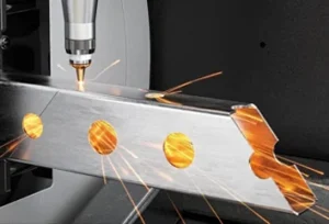
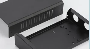
Tube frame cut parts can meet their individual cutting requirements and still delay assembly. Similar members may be mixed, left- and right-hand parts may be confused, or a delivery may contain enough pieces overall but not the right quantities for each frame.
A useful cut-part kit connects each physical component to its drawing, bill of materials and assembly orientation. This guide is for equipment manufacturers buying tube components for their own fit-up or welding, with particular attention to identification and handover.
Quick answer: Synchronise the assembly drawing, part files and BOM revisions. Separate quantity per set from total order quantity, identify non-interchangeable parts, define orientation from clear references, and agree identification and packing requirements. Confirm who checks the first set before the remaining components enter assembly.
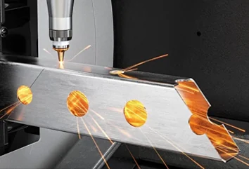
Lumen Future’s metal tube and profile laser cutting service can review drawing-based components with end cuts, holes, slots and notches. Individual marking, set-based packing, packing-list detail and supplier pre-assembly should be requested and confirmed in the quotation; they are not assumed inclusions in every cutting order.
Define What One Kit Includes
A tube frame cut-part kit is an agreed collection of components for a defined assembly. It is not automatically a welded frame, a complete hardware package or a structurally validated design. Start by identifying whether one set represents a complete frame or a named subassembly.
List the supply boundaries. Does the kit contain tubes only, or also foot plates, brackets and connection plates? Are fasteners supplied separately by the customer? Are parts delivered as cut, deburred, tapped or finished? A cut hole is not automatically a threaded or precision-finished hole.
Similarly, prepared joint geometry does not mean the parts have been assembled or welded. If the customer will carry out those operations, state that clearly. If supplier fit-up or another operation is requested, agree its extent, acceptance criteria and documentation before production.
Connect the Assembly Drawing, Part Drawings and BOM
Tube frame fabrication drawings need a consistent link between the assembly and the individual components. The bill of materials, or BOM, supplies that link only when its identifiers and revisions agree with the drawing package.
| Document | What it should communicate |
|---|---|
| Assembly drawing or model | Component positions, orientation, connections and assembly references. |
| Individual part drawing and model | The released geometry, material, profile, wall thickness and manufacturing requirements for each part. |
| BOM | Part number, revision, description, quantity per set and the applicable supply scope. |
| Packing list, where agreed | Delivered identities and quantities, package references and any shortages or separately supplied items. |
An assembly item number should lead to a BOM entry, which should lead to the correct part file. The physical identification should support the same relationship. Similar filenames or matching tube lengths do not establish that two parts are interchangeable.
For multi-face features, provide the relevant three-dimensional geometry and controlled drawing rather than relying on unlabelled flat views. The tube laser cutting RFQ checklist covers the broader file and specification package; this article focuses on keeping those identities intact through delivery and assembly.
Separate Quantity per Set From Total Order Quantity
State the required number of frame sets and the quantity of each component in one set. Keep spare and trial pieces separate so that an assembler does not mistake them for additional required members.
| Part | Per set | Sets | Required | Spares | Total |
|---|---|---|---|---|---|
| T-101 cross-member | 2 | 3 | 6 | 1 | 7 |
| T-102-L left upright | 1 | 3 | 3 | 0 | 3 |
| T-102-R right upright | 1 | 3 | 3 | 0 | 3 |
In this example, seven cross-members do not mean each frame uses more than two. One is an explicitly identified spare. Also state whether a first trial set is included in the order or additional to it.
When components are shared across subassemblies, confirm whether the BOM is grouped or consolidated so quantities are not counted twice. Update the purchase order and released list together if set counts change. A correct total piece count cannot compensate for a shortage of one non-interchangeable part.
Distinguish Identical, Mirrored and Similar-Looking Parts
Three situations need different handling: genuinely identical parts used in several positions, mirrored parts that cannot be exchanged, and equal-length parts with different holes or end features.
For example, two square tubes may have the same length and end cuts but mounting holes on different faces. Sorting them by length alone would lose the distinction. Give non-interchangeable components separate controlled identities, such as distinct part numbers or an explicitly managed variant system.
Rotating a member does not necessarily turn a left-hand component into a right-hand one. Review the complete feature arrangement, including its relationship to both ends. Do not merge mirrored files merely because their stock profile and overall dimensions match.
Conversely, if one identical component is intentionally used in several orientations, keep that distinction in the assembly instructions rather than inventing contradictory manufacturing requirements. Part identity answers “which component?”; assembly position answers “where does it go?”.
Define Orientation From a Named End and Reference Face
Use a defined viewing direction. “Rotate clockwise” is ambiguous if one person looks from the opposite end of the tube. Identify an end and a reference face, then show the relationships between holes, slots, notches and angled cuts.
- Label the end from which the orientation is viewed.
- Identify the reference face or angular reference used by the drawing.
- Relate features on different faces to the same reference system.
- Identify visible-face or tube-seam requirements only where they matter to function or finish.
- Keep left/right and front/back descriptions consistent with the assembly view.
A square outer profile does not make every face functionally equivalent once holes and joints are added. Round tubes likewise need a defined angular relationship when features must align with other components. Any physical direction mark and its location should be approved rather than added informally.
The tube laser cutting design guide explains feature and joint considerations. For handover, the objective is to preserve the approved orientation information so the assembler does not need to reconstruct it from appearance.
Agree Part Identification Before Packing
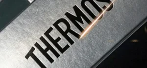
Possible approaches include individual labels, tags, bundle labels or approved permanent marking. Select the method according to when identification is needed and what happens to the part afterwards. Do not assume every tube cutting kit includes automatic individual laser marking.
Agree what the identification contains: part number, revision, set identity or direction reference. These fields serve different purposes. A part number may identify every identical cross-member, while a set identifier allocates one of those members to a particular frame.
Consider whether identification will remain readable after unpacking, handling, cleaning or coating. A bundle label can identify a group at receipt but cannot distinguish loose similar parts once they are mixed at an assembly station. If identification must survive that stage, specify a suitable arrangement.
Confirm permissible marking or label locations and any restricted surfaces. Do not add an engraved groove, punched dot or notch without approval: an identification feature still changes the component. Adhesive labels and residues also need consideration where subsequent surface preparation is important.
Choose Set-Based or Part-Based Packaging
“Supplied as kits” does not necessarily mean one box per frame. Long members may need bundles while short components travel in smaller packages. Agree how those packages remain connected to the set.
| Approach | Useful when | Handover requirement |
|---|---|---|
| Grouped by set | Assemblers need to issue one frame’s components together. | Identify the set and any associated additional packages. |
| Grouped by part number | Repeated components are stored and picked for batch assembly. | Provide the controlled quantities needed to allocate each set. |
| Hybrid grouping | Long members and small components need different packing. | Maintain the connection between bundles, boxes and assembly sets. |
For a set split across two packages, the package references should make the relationship clear. Separate different revisions and any items awaiting correction. Identify spares independently instead of leaving an unexplained extra component in a production set.
Packaging should protect vulnerable end features and account for handling of long members, not only avoid cosmetic rubbing. Confirm package size, weight and receiving arrangements where they constrain delivery. The practical method and any associated cost should be agreed for the project.
Check the First Set Before Welding
First-set fit-up is a check of the intended component relationships before permanent joining. Agree who performs it, which mating parts or fixtures are available, what will be checked and whether further production waits for approval. Supplier pre-assembly is not assumed unless explicitly included.
- Reconcile identities, revisions and quantities against the BOM.
- Confirm mirrored parts and the specified end and face orientations.
- Arrange components according to the assembly drawing using suitable support.
- Check critical mounting interfaces, joint relationships and specified gaps.
- Record interference, unexpected gaps or any need to force parts into position.
- Resolve discrepancies before permanent joining or unapproved trimming.
- Update released drawings and records for any approved change.
Fit-up is not final frame acceptance. Locating tabs and slots can assist assembly but do not automatically eliminate fixtures or inspection. Correct pre-weld fit does not demonstrate post-weld dimensions, weld quality or structural capacity.
Likewise, a successful first set does not establish that every later part has the correct identity or geometry. Agree continuing checks in proportion to the requirements. Where the supplier receives no mating equipment or assembly fixture, component inspection cannot be described as a complete equipment fit test.
Control Revisions and Partial Deliveries
When a component changes, identify which sets are affected and whether old and new revisions may be used together. Interchangeability needs approval; matching length is not sufficient evidence. Keep superseded or held parts separate from released replacements.
For a partial delivery, list what has arrived and what remains outstanding. Do not label a shipment as a complete kit if a required component is still missing. Where assembly sequencing matters, identify the components needed to start a usable subassembly.
At handover, treat three results separately: quantity completeness, correct identity and conformance to the agreed requirements. A package count or a signed delivery note alone does not demonstrate all three. Confirm any packing list, inspection report or material documentation required with the order.
What to Send for a Tube Frame Kit Quote
- Assembly drawing or model showing component relationships.
- Individual part files with controlled identifiers and revisions.
- BOM with quantities per set and included supply scope.
- Required number of sets, trial quantities and separate spares.
- Material grade, tube section and wall thickness for each part.
- Mirrored-part, reference-face and orientation requirements.
- Requested identification, packaging and inspection arrangements.
- Delivery plan and responsibility for first-set fit-up and welding.
For laser cut tube frame components, these handover details should be reviewed alongside the cutting geometry. Resolve conflicting revisions and unanswered orientation questions before issuing the production release.
Frequently Asked Questions
Is a tube cutting kit the same as a welded frame?
No. A kit is an agreed set of components. Welding, finishing, hardware, pre-assembly and final frame inspection are separate scope items unless the quotation includes them.
Do left- and right-hand components need different identifiers?
Non-interchangeable parts need an unambiguous controlled distinction. Separate part numbers or a clearly managed variant system can provide it; the assembly and packing information must use the same convention.
Must every part be permanently marked?
Not necessarily. Choose identification based on handling, traceability and subsequent processing. Confirm the method and permitted location rather than assuming individual laser marking is included.
Can self-locating slots replace assembly fixtures?
Not automatically. They may assist positioning, but support, joint control, welding and inspection requirements still need review for the actual assembly.
Should components be packed by part number or frame set?
Either approach, or a hybrid, may be appropriate. The important requirement is a clear connection between physical packages, part identities, quantities and the intended assembly sets.
Plan Your Tube Frame Cut-Part Kit
Send the assembly drawing, part list and required number of sets. Include orientation, identification and packing requirements so the cutting and handover scope can be reviewed together.