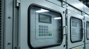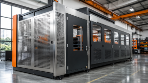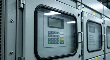
Control panel fabrication turns an approved mechanical design into door panels, mounting plates, gland plates, cut-outs and formed enclosure components that are ready for hardware installation and electrical integration. Good results depend on coordinating the cut geometry with bends, hinges, locks, inserted fasteners, finishes and final fit—not simply cutting the outline from sheet metal.
Quick answer
Lumen Future supports drawing-based sheet metal fabrication for suitable control panels and electrical enclosure components in Singapore. A project may combine laser cutting, deburring, CNC bending, welding, mechanical hardware, surface finishing and laser marking according to the approved scope. Send a revision-controlled STEP model and PDF drawing, plus DXF files where available, and identify the material, thickness, quantity, critical cut-outs, hardware and finish.
Electrical circuit design, component selection, wiring, PLC programming, regulatory approval and certified enclosure performance are not automatically included in a metal-fabrication quotation. For project-specific review, visit our sheet metal laser cutting service.
What Does Control Panel Fabrication Include?
The phrase control panel fabrication can describe several different deliverables. One supplier may provide only a flat operator panel, another a welded enclosure shell, and a system integrator may deliver a wired and tested electrical cabinet. The quotation should state the handover point clearly.
| Possible deliverable | Typical metal-fabrication work | Information that still needs agreement |
|---|---|---|
| Flat operator or face panel | Cut profile, HMI opening, push-button holes, connector cut-outs and deburring | Critical locations, edge condition, visible face and marking |
| Formed panel | Laser cutting followed by bending and hardware insertion | Bend radius, flange dimensions, hardware type and final inspection stage |
| Enclosure body or door | Cutting, bending, welding, grinding and an agreed finish | Door gap, hinges, lock, gasket interface and cosmetic criteria |
| Mounting backplate | Plate cutting, mounting holes, studs or inserted fasteners | Datum scheme, component layout, flatness and grounding provisions |
| Gland or cable-entry plate | Cut-outs for cable glands, bulkhead connectors and removable panels | Gland specification, sealing interface, orientation and access |
| Marked panel | Port names, switch labels, serial numbers, logos or machine-readable codes | Approved artwork, contrast, position, durability and acceptance method |
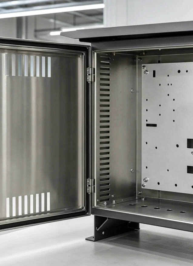
Know the Parts of the Enclosure
Separating the enclosure into controlled parts makes quotation, revision management and inspection easier. It also prevents an opening that fits one purchased component from being copied into the wrong panel or revision.
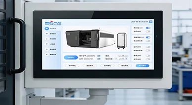
Designing HMI, Button, Fan and Connector Cut-Outs
A cut-out must fit more than the visible front of a component. The design should account for the manufacturer’s mounting geometry, clips or studs, connector body, cable bend radius, tool access and future replacement. A clean opening can still fail at assembly if the rear housing clashes with a bend, rail or adjacent component.
| Feature | Confirm before release | Common problem |
|---|---|---|
| HMI or display | Panel opening, corner radii, bezel overlap, fasteners, rear depth and connector access | Using the screen size instead of the manufacturer’s panel-cut dimension |
| Push button or selector | Nominal hole, anti-rotation feature, collar clearance and label space | Correct diameter but missing keyway or crowded legends |
| Fan and filter | Airflow direction, opening, hole pattern, guard, filter access and nearby stiffness | Vent pattern weakens a large door or conflicts with internal equipment |
| Connector | Body outline, flange, screw pattern, mating direction and plug-removal space | The connector fits the opening but cannot be inserted or serviced |
| Cable gland | Gland standard, thread or locknut, plate thickness, spacing and sealing face | Insufficient wrench access or inconsistent cable-entry orientation |
| Ventilation slots | Slot geometry, open area, guarding, edge distance and environmental requirement | Dense slots create distortion, weak ligaments or an unverified ingress path |
Use the controlled component drawing rather than measuring a catalogue image. When a purchased part may change, identify its manufacturer and part number in the assembly documentation so the cut-out can be checked before repeat production.
Cut-Outs Near Bends, Edges and Hardware
There is no responsible universal value for every hole-to-edge or hole-to-bend distance. The practical limit depends on material, thickness, bend radius, tooling, grain direction, cut geometry and the required appearance. Treat any general design ratio as an early screening rule and confirm the production geometry through DFM.
| DFM risk | Possible result | Recommended drawing action |
|---|---|---|
| Cut-out intersects the bend-affected zone | Opening stretches, shifts or becomes difficult to gauge after forming | Dimension the functional opening in the formed condition and identify the bend |
| Hole too close to an edge | Weak ligament, local distortion or difficult hardware seating | Show the functional edge distance and fastener load context |
| Pressed fastener conflicts with a bend | Insufficient tool access or a distorted flange | Provide the exact fastener series, orientation and installation stage |
| Dense vent pattern in a wide panel | Loss of stiffness, local wave or visible oil-canning | Review remaining ligaments, stiffening and acceptable flatness |
| Lock or hinge conflicts internally | Door cannot close, fasteners clash or wiring space is lost | Include hardware envelopes in the STEP assembly |
| Coating allowance omitted | Tight openings, blocked threads or poor electrical contact | Identify coated and masked surfaces plus final-fit requirements |
For general hole, slot, tab and edge-distance principles, see our sheet metal laser cutting design guide. For high-accuracy holes, identify which openings may require drilling, reaming or machining after the laser blank is produced.
Selecting Sheet Metal for a Control Enclosure
Material selection should follow the installation environment, structural need, weight, electrical interfaces, finish and lifecycle—not a simple assumption that one metal is always superior.
| Material | Why it may be selected | Points to review |
|---|---|---|
| Mild steel | Economical formed construction, weldability and compatibility with many coating systems | Corrosion protection, coating coverage, cut edges, weld preparation and grounding points |
| Stainless steel | Corrosion resistance, cleanability and durable exposed surfaces | Grade, brushed direction, weld tint, passivation or polishing, film protection and chloride exposure |
| Aluminium | Lower weight, natural corrosion resistance and suitability for selected electronics housings | Alloy and temper, bend behaviour, welding, galvanic contact, anodizing and grounding strategy |
| Galvanized steel | Useful for selected indoor cabinets, backplates and equipment parts | Exposed cut edges, forming, welding fumes, coating repair and final finish compatibility |
For indoor automation equipment in Singapore, mild steel with a specified coating may be sufficient. Stainless steel or aluminium may be considered where corrosion, cleaning, weight or appearance drives the decision. Coastal, washdown, chemical and outdoor conditions require a project-specific review; Singapore’s climate alone does not make one grade correct for every installation. Our stainless steel fabrication page covers grade and process selection in more detail.
A Typical Manufacturing Route
The route changes with the design. A flat engraved faceplate may need only cutting, deburring and marking. A welded cabinet may require multiple bend operations, fixtures, controlled welding, weld dressing, coating, masked interfaces, hardware and final mechanical fit checks.
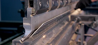
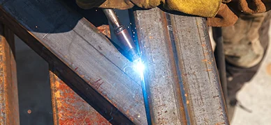
Process order matters. An inserted fastener may need to be installed before coating, while a thread or electrical contact face may require masking. A label marked through a coating behaves differently from a mark applied to bare metal. Welding can move door frames and panel openings even when every flat blank passed cutting inspection.
Hinges, Locks, Studs and Inserted Fasteners
Specify hardware by controlled manufacturer part number where possible. A generic note such as “M4 insert” may not define the head style, required sheet thickness, material, installation side or surface condition.
- Hinges: identify the type, pin direction, door opening angle, mounting method and removable-door requirement.
- Locks and handles: provide the cut-out, anti-rotation details, engagement geometry and internal operating envelope.
- Self-clinching fasteners: state the series, thread, sheet compatibility, installation face and relationship to bends.
- Weld studs: define stud material, location, weld side, projection and any finish or grounding function.
- DIN-rail and component mounts: control the mounting pattern, standoff height and orientation relative to cable routing.
- Grounding points: identify the required hardware and areas that must remain electrically functional after finishing.
Finishing, Masking and Panel Identification
| Finish or operation | Typical reason | Details to specify |
|---|---|---|
| Powder coating | Colour, appearance and corrosion protection on suitable steel or aluminium parts | Colour reference, texture, visible faces, coating exclusions, thread masking and mating fit |
| Anodizing | Selected aluminium appearance and surface protection | Alloy, colour, cosmetic face, electrical-contact areas and dimensional interfaces |
| Brushed stainless finish | Directional cosmetic surface for exposed equipment | Grain direction, reference sample, visible face, weld blending and protective film |
| Grinding or weld dressing | Remove sharp edges, prepare surfaces or blend agreed joints | Areas to treat, acceptable witness marks and final finish requirement |
| Laser marking | Port labels, device functions, serial numbers, logos and traceability | Artwork, location, orientation, contrast, durability and acceptance method |

Visit our polishing and grinding and laser engraving pages for related finishing and identification options. Where a finish is arranged through a project partner, that responsibility should be identified in the quotation rather than presented as an automatic in-house operation.
Why Fabrication Alone Does Not Establish an IP Rating
An enclosure’s resistance to access, dust or water is a system-level result. It depends on the complete design and tested configuration: seams, door overlap, gasket material and compression, latches, hinges, cable glands, filters, connectors, welds, drainage, assembly and installation.
IEC 60529 classifies degrees of protection provided by enclosures for electrical equipment. Supplying sheet metal parts that match a drawing does not by itself demonstrate that the completed enclosure meets a particular IP code. If an IP requirement applies, the customer should define the governing standard, target rating, controlled components, assembly responsibility and required verification or test evidence.
Inspect the Stage That Controls Function
Inspection should follow the manufacturing state that matters to assembly. Checking only the flat laser blank cannot prove that a welded, coated and hardware-fitted enclosure will close correctly.
| Stage | Useful checks | What it cannot prove alone |
|---|---|---|
| After laser cutting | Profile, critical cut-outs, hole pattern, burr and edge condition | Final bend position, door fit or welded enclosure geometry |
| After bending | Flange dimensions, angles, orientation and cut-out relationship | Movement introduced by welding or coating |
| After welding | Overall dimensions, diagonals, frame opening, distortion and joint appearance | Final fit after coating, gasket and hardware installation |
| After finishing | Colour, visible surfaces, masking, threads and coating interference | Electrical function or an IP classification without the defined test route |
| After mechanical assembly | Door gap, hinge travel, latch engagement, inserts and agreed hardware | Electrical safety, wiring performance or system programming |
Identify critical characteristics on the drawing rather than tightening every dimension. Door fit, HMI position, mounting interfaces, gasket contact and connector relationships may deserve controlled datums and dedicated checks. General tolerances should be stated intentionally; they do not replace functional requirements. See our quality assurance approach for project-based inspection planning.
What Files Should You Send?
If the 3D model, DXF and drawing conflict, state which document governs and resolve the discrepancy before production. A released revision should replace—not merely accompany—obsolete geometry.
Singapore Control Panel Fabrication RFQ Checklist
Automation projects in Singapore often combine local installation with imported HMIs, drives, connectors or sealing components. Sharing the complete mechanical context reduces questions during fit-up and avoids opening changes after coating.
Frequently Asked Questions
Can you fabricate only the metal enclosure without electrical wiring?
Yes. A project can be quoted for drawing-based metal components or a mechanically assembled enclosure without electrical wiring, programming or control-system integration. The quotation should identify the exact fabrication and handover scope.
What files are needed for a custom control panel enclosure?
A STEP model and revision-controlled PDF drawing are recommended, with DXF profiles for applicable flat parts. Include material, thickness, quantity, critical cut-outs, hardware, finish, visible faces, tolerances and inspection requirements.
Can HMI, fan, button and connector openings be laser cut?
Many panel openings can be laser cut when the geometry, material, thickness and edge requirements are suitable. Provide the purchased component reference and controlled cut-out dimensions so mounting clearance and nearby bends can be reviewed.
Can bending, welding and inserted hardware be included?
They can be included where suitable and stated in the quotation. Provide the exact fastener, hinge, lock and stud specifications, installation direction, supply responsibility and required inspection stage.
Can powder coating or stainless steel finishing be arranged?
Suitable finishing can be reviewed as part of the project route. Define colour or surface reference, visible faces, grain direction, masking, grounding points, thread protection and cosmetic acceptance. The quotation should state whether a finish is completed directly or coordinated through a partner.
Does a fabricated enclosure automatically meet an IP rating?
No. An IP rating depends on the complete enclosure design, seams, door, gasket, locks, glands, filters, connectors, assembly and defined verification. Fabricating sheet metal parts to a drawing does not by itself certify the completed enclosure.
Send Your Control Panel or Enclosure Drawing
Share the STEP model, controlled drawings, material, thickness, quantities, cut-out schedule, hardware and finish. We will review the sheet-metal manufacturing route and clarify the quoted scope before production.
Technical references: IEC 60529, Degrees of protection provided by enclosures (IP Code); ISO 2768-1, general tolerances for linear and angular dimensions without individual indications. The applicable edition, acceptance criteria and verification route must be defined by the project documents.