

Each tube in a frame can be cut to drawing while the completed assembly still fails to bolt to its machine. Welding may change the position of a foot plate, the distance between rails or the alignment of a mounting pattern. For custom welded tube frames for equipment, the purchase specification therefore needs to define the finished frame, not only the individual cut parts.
This guide is for equipment engineers and buyers preparing a welded tube frame fabrication enquiry in Singapore. It focuses on drawings, fit-up and inspection of the supplied frame. It is not a structural design or load-calculation guide.
Quick answer: Send a controlled assembly PDF and, where available, a STEP model, with matching part drawings and a bill of materials (BOM). Mark the equipment mounting faces, locating features and dimensions that must still be correct after welding. Agree the measurement condition, first-frame approval and final inspection records before production. A successful pre-weld fit-up alone does not establish that the released frame will install correctly.
First, Define What You Are Buying
A kit of labelled tube components is not the same deliverable as a finished welded equipment frame. A tube frame cut-part kit is organised for the customer’s later assembly; a welded frame also requires agreed joint, geometry and finished-interface checks.
| Supply scope | What to specify | What it does not establish |
|---|---|---|
| Cut components | Profile, material, end cuts, holes, part ID and quantity. | Final frame geometry or weld quality. |
| Welded frame | Component scope plus joint requirements, assembly datums, finished dimensions and inspection condition. | Load capacity or installation unless separately designed and agreed. |
| Welded and finished frame | The above plus clearly listed grinding, cleaning, coating or other finishing, and any affected rechecks. | Unspecified post-weld machining, certification or on-site work. |
Write the quotation boundary plainly: Are foot plates and brackets included? Are fasteners customer-supplied? Is a trial frame required? Who checks fit against the mating machine? If a post-weld operation is essential, list it rather than treating “complete frame” as an all-inclusive instruction.
Engineering boundary: The responsible designer must establish loads, stability, fatigue, guarding and any applicable regulatory or certification requirements. Lumen Future reviews fabrication suitability by project. Heavy structural, load-bearing and certification work is not automatically included in a normal equipment-frame quotation.
Build One Coordinated Drawing Package
Send an assembly view that explains how the members relate to each other and to the equipment. A set of unrelated DXF files may define cut shapes but not which face is front, where the machine sits or which two holes must align across the welded assembly.
| Document | Useful information | Question it answers |
|---|---|---|
| Assembly PDF and, where available, STEP model | Overall arrangement, orientation, equipment envelope, mounting datums and finished critical dimensions. | Will the completed frame install as intended? |
| Part drawings | Tube section, outside dimensions, wall thickness, material grade, end features, plates and brackets. | What must be cut and prepared? |
| BOM and revision list | Part numbers, left/right identity, per-frame quantity, total frame quantity and released revision. | Are the correct parts being joined in the correct configuration? |
| Weld and finish notes | Joint locations and design requirements, restricted faces, visible areas and specified post-weld operations. | What fabrication and appearance scope is required? |
| Mating-part information | Equipment hole pattern, locating pins, floor or base contact, fastener access and adjacent clearances. | Which interfaces control acceptance? |
Use consistent units (typically mm), drawing numbers and revisions across the model, PDF and BOM. If files disagree, identify the governing released drawing and resolve the conflict before manufacture. The tube cutting RFQ checklist covers cut-component inputs; this frame-level package adds the welding and installation requirements.
State whether the tube is circular hollow section (CHS), square hollow section (SHS) or rectangular hollow section (RHS), then give its exact size, wall thickness and grade. Do not rely on “standard steel tube” as a sufficient material specification. If choosing a section is still part of the design discussion, see the round versus square and rectangular tube guide; the final section choice remains the customer’s engineering decision.
Dimension the Frame From Its Installation Datums
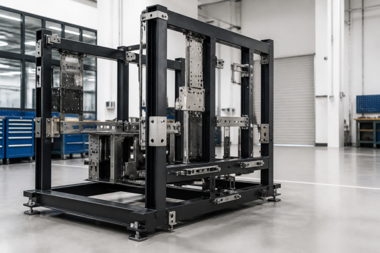
An outside length, width and height are useful for space planning, but they do not prove fit. Identify the faces and features that actually locate the frame: foot pads or base faces, a primary locating hole or slot, rail positions, motor or guard brackets, and clearance openings. Define the critical relationships to those references on the finished assembly drawing.
For example, consider a machine frame with four feet and two cross-members. The tube cuts might all be correct, yet a shifted rear foot prevents the mounting bolts from entering. A drawing that checks only the tube lengths will miss the problem. The functional requirement is the final foot-hole pattern relative to the agreed seating plane and locating features.
Specify whether the frame is measured free-standing after fixture release, resting on defined supports, or under a particular installed restraint. A frame clamped tightly in a weld fixture can behave differently once released. Do not assume that forcing bolts into misaligned holes is an acceptable installation method. If several pads must contact the mating base, identify any required relationship between them and how it will be checked.
Mark which dimensions are truly assembly-critical and which are general envelope dimensions. If a drawing uses a general weldment-tolerance standard such as ISO 13920:2023, state the selected class and applicable drawing requirements. That standard bases class selection on function and says the applicable tolerances are those stated on the drawing; it does not justify a universal tolerance promise for every frame.
Review Fit-Up, Weld Access and Process Before Release
Fit-up should be reviewed against the assembly references, not judged only by whether the parts can be pulled together with clamps. Before welding, verify part identity, left/right orientation, tube-to-plate position, joint gaps, edge mismatch, weld access and any areas where a later component would block the joint.
Joint design, material, thickness, access and finishing requirements influence whether laser, TIG or MIG welding is suitable for a particular frame. Lumen Future lists all three as in-house capabilities, but the process and acceptance scope are confirmed after drawing review through its welding and assembly service. Do not specify laser welding solely because the tubes were laser-cut, or assume one method is appropriate for every joint.
Fixtures, tack sequence and weld sequence may be considered to manage movement, but none makes distortion disappear. TWI’s fabrication guidance explains why assembly technique and welding sequence matter. The project drawing should state the required result; the production method must then be reviewed against that result. If a critical hole or mounting face will need post-weld machining, make it an explicit quoted operation and check that access is possible.
Where the frame includes end plates or base plates, use the tube end-plate and mounting-interface guide for the local tube-to-plate questions. This article addresses the relationships across the whole frame.
Agree a First-Frame and Final Inspection Plan
Inspection should follow the stage at which a requirement becomes meaningful. A cut-part dimension is not a substitute for a post-weld mounting dimension, and a visually neat weld does not prove load capacity or hidden weld integrity.
| Stage | Typical agreed checks | Decision to record |
|---|---|---|
| Cut parts | Material and part identity, length, end features, holes and released revision. | Are the correct components ready for fit-up? |
| Pre-weld fit-up | Orientation, joint access, plate location, gap and the most important equipment interfaces. | Can the first arrangement be joined without a drawing change? |
| After welding, cooling and fixture release | Specified weld appearance, final hole patterns, mounting faces, rail or bracket locations and any relevant diagonal, squareness or overall dimensions. | Does the finished frame meet the agreed drawing in the stated measurement condition? |
| After finishing | Interfaces affected by coating, grinding, cleaning or other operations, plus required packaging protection. | Is the delivered condition the approved condition? |
Agree the measurement method, reference surfaces, acceptance values, sample frequency and records before production. If an actual mating component or customer fixture is needed for a fit check, state who supplies it and when. If a first frame is to be approved before the balance of an order, identify the approving person and drawing revision. A first-frame check is not a substitute for an agreed repeat-production control plan.
Visual checking of welds and dimensional inspection answer different questions. If a project calls for a particular weld-inspection standard, additional non-destructive testing, procedure qualification or certification, include those requirements in the RFQ for separate review. They are not implied by an ordinary visual or dimensional check. Lumen Future’s quality assurance page describes the broader inspection approach; the actual evidence supplied must be agreed for the order.
Include Delivery and Handling in the Frame RFQ
A finished frame may be harder to move than its separate members. Give the delivery location in Singapore, the number of frames, maximum access opening or lift limitations, and any orientation or protection needs. Identify machined or visible interfaces that must not be used as lifting or contact points. Confirm whether the order is for delivery or collection and whether any site unloading is expected. Do not assume installation, lifting equipment or a fixed lead time is included without quotation.
Welded Tube Frame Fabrication RFQ Checklist
For a useful first review, send:
- A controlled assembly PDF and STEP model where available, showing units, revision and frame orientation.
- Matching tube, plate and bracket drawings plus a BOM with part IDs and per-frame quantities.
- Tube profile (CHS, SHS or RHS), outside dimensions, wall thickness, grade and any material-documentation requirement.
- The mating equipment drawing, mounting faces, locating features, critical dimensions and specified tolerances.
- Joint locations and design or acceptance requirements established by the responsible engineer.
- Any first-frame fit-up, customer fixture or mating-part check required before further production.
- Post-weld machining, cleaning, grinding, coating and restrictions on functional or cosmetic faces.
- Final measurement condition, inspection characteristics, sampling and required records.
- Any load, test, regulatory or certification requirement for separate feasibility review.
- Frame quantity, target date, Singapore delivery or collection point, access and packaging constraints.
If the drawing package is incomplete, identify what is missing and send photographs of the equipment and mounting area to explain the context. Photos can support a review, but they cannot replace confirmed dimensions or a released assembly drawing for a critical fit.
Frequently Asked Questions
Are laser-cut tube parts the same as a finished welded frame?
No. Individual parts can pass their cut checks while the welded assembly misses its mounting interfaces. Specify whether you need a cut-part kit or a frame accepted to finished-assembly requirements.
Should critical holes be completed before or after welding?
There is no universal sequence. It depends on the required final position, available access and manufacturing route. State the finished hole requirement and let the method be reviewed before quoting any additional operation.
Can the frame be accepted while clamped in a fixture?
Only if that is the agreed acceptance condition. Production fixture readings may be useful, but final acceptance should reflect the specified free-standing, supported or installed condition.
Does a visual weld check prove the frame’s load capacity?
No. Appearance, dimensional fit and structural adequacy are separate questions. Load performance and any required certification must be established through the responsible design and separately agreed verification scope.
Can I request TIG or MIG instead of laser welding?
Yes, state the requested process and why it matters. Lumen Future provides laser, TIG and MIG welding in-house, with suitability confirmed for the material, joint and project requirements before quotation.
Send Your Equipment-Frame Drawings
Share a controlled assembly PDF and, where available, a STEP model, plus matching part drawings, tube sections, material, quantity and the interfaces that must fit after welding. Highlight any first-frame trial, inspection record, finish or delivery requirement. We will review the fabrication scope and advise what needs confirming before quotation.