Tube end plate fabrication needs more than a plate outline and a tube length. The tube, plate and mating equipment must share clear positioning references, mounting details and acceptance requirements. Otherwise, individually correct parts can still leave an assembly with inaccessible bolts, the wrong orientation or an unsuitable contact face.
This guide is for equipment designers and purchasers preparing tube mounting plates, adapter plates and related components for fabrication in Singapore. It focuses on the information needed before cutting and assembly, rather than structural connection calculations.
Quick answer: Review the tube drawing, end plate drawing and mating interface together. Define orientation, mounting-hole positions, fastener access and the finished condition of contact faces. State whether the order covers separate cut parts or an assembly, then agree which dimensions are checked before and after joining or finishing.
Define the End Plate’s Function and Supply Scope
A closure cap and a mounting end plate are not interchangeable specifications. A cap may simply close a tube opening. A mounting plate connects the tube to another component, while a base or adapter plate may connect that assembly to a larger machine. The drawing must explain the intended function, not rely on the part name.
Start by stating what you want delivered: separate tube and plate components, a matched collection for customer assembly, or a joined assembly for process review. Identify who supplies fasteners, who performs fit-up and who verifies the final installation.
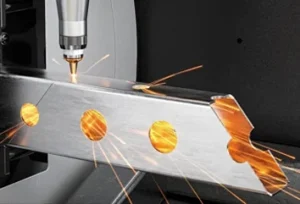
Lumen Future’s tube and profile laser cutting service supports review of drawing-based tube features. End plate outlines and mounting patterns can be reviewed through the sheet and plate laser cutting service. Additional joining, hole finishing or surface operations need to be included explicitly in the quotation.
Design boundary: This is a fabrication drawing checklist, not a guide to selecting load-bearing plate thickness, weld size, bolt grade or building anchors. The responsible designer must establish structural and safety requirements. Manufacturing review and trial fit do not constitute load certification.
Review Three Drawing Sets Together
A plate DXF can describe a cutting contour without explaining where the tube sits or what the finished component connects to. Supply the assembly relationship as well as the individual geometry.
| Drawing or model | Information to include | Question it resolves |
|---|---|---|
| Tube component | Profile, wall thickness, material, ends, holes and orientation references. | Which tube face or feature must align with the plate? |
| End plate | Material, thickness, outline, mounting holes, locating features and controlled dimensions. | What is being cut, and which features control fit? |
| Mating interface and assembly | Equipment mounting pattern, contact face, position, surrounding space and assembly sequence. | Will the complete component connect as intended? |
Keep units, part numbers and revisions consistent across the package. A three-dimensional model helps explain spatial relationships; a controlled PDF drawing communicates material, critical dimensions, tolerances and inspection notes. Identify the governing document if files disagree, and resolve discrepancies before release.
Where a plate inserts into a tube or closely follows its contour, confirm the actual stock profile. Nominal outside dimensions alone do not describe internal corner geometry or every feature affecting clearance. Request relevant profile information or sample review where fit depends on it.
Locate the Tube From Clear Assembly References
Show whether the tube is centred on the plate or intentionally offset. Define its angular relationship to the mounting face and the direction of holes, slots or other asymmetric features. State whether the tube end is flush, projecting or inserted into the plate.
Use agreed drawing datums or clearly identified reference features. Avoid a collection of unrelated dimensions taken from whichever edge happens to be convenient. The supplier needs to understand which relationships determine installation, not merely the overall envelope.
Illustrative example: A square tube has a side access hole and connects to a rectangular mounting plate. The tube can be centred correctly yet rotated so the access hole faces an obstruction. A labelled assembly view showing the access side prevents an ambiguity that the plate outline cannot resolve. This is a drawing example, not a customer case or tolerance claim.
For left- and right-hand parts, use distinct identifiers and views. A mirrored arrangement may look similar but place the mounting pattern or access hole on the wrong side. For detailed feature-design considerations, see the tube laser cutting design guide.
Check Mounting Holes and Installation Tool Space
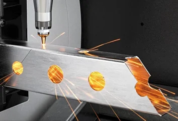
For tube mounting plates, hole diameter and pitch are only part of the interface. Identify whether each hole provides fastener clearance, location or another function. A cut hole should not be assumed to include a thread, countersink or precision finishing operation unless specified and accepted.
- Locate the pattern relative to the tube and the actual mating equipment.
- Show the intended bolt insertion direction and the space occupied by nuts and washers.
- Check whether the tube, joint area or neighbouring component obstructs a hole.
- Confirm that the selected spanner or socket can reach the fastener during the intended assembly sequence.
- Identify fasteners that must be inserted before the next component is attached.
A bolt passing through a hole does not prove that it can be tightened. Use the customer’s actual hardware and tool envelope when checking access; there is no single clearance distance appropriate for every connection.
If the interface must match an existing machine, provide the controlled mating drawing or confirmed measurements. Photographs help explain obstructions but do not establish precise hole coordinates or scale.
Specify Contact Faces in Their Final Condition
Mark the face that contacts the equipment. Distinguish it from a cosmetic face and from surfaces that do not control assembly. State any required flatness, angular relationship, coating exclusion or surface condition using the customer’s drawing and acceptance requirements.
For a steel tube end plate, clarify whether the interface is accepted as cut, after joining or after its specified finish. These are different inspection conditions. If paint or another finish is planned, identify areas where its presence would affect the intended fit.
Do not assume that a laser-cut blank automatically provides a precision-finished mounting face. If an additional face-finishing or machining operation is required, identify it for separate capability and process review. It is not an automatic inclusion in a cutting or welding order.
Confirm Joining Suitability Before Ordering an Assembly
If you need a joined component, submit the joint detail, material combination, thicknesses, access constraints and finished assembly requirements. The quotation should distinguish cutting work from the joining and inspection scope.
Lumen Future’s dedicated laser welding service requires application review. Laser welding should not be assumed suitable for every tube-to-plate connection, particularly where the required joint or fit-up falls outside the confirmed process scope. Do not treat the service as an automatic offer of TIG, MIG or heavy structural welding.
The responsible designer should supply the connection requirements. Fabrication review can identify process questions, but it does not replace engineering validation of the connection. If the requested joining route is unsuitable, resolve the scope before committing to production.
Separate Single-Part Checks From Assembly Acceptance
Tube frame mounting details should state when their critical relationships are verified. A successful loose fit-up does not establish the final condition after joining and finishing.
| Stage | Typical agreed checks | What it does not establish |
|---|---|---|
| Cut components | Part identity, outline, holes, end features and drawing revision. | Final assembled alignment or mounting-face condition. |
| Pre-joining fit-up | Tube position, orientation, joint fit and installation access. | Unchanged geometry after joining or finishing. |
| Finished assembly | Specified interface dimensions, contact-face requirements and agreed inspection records. | Load capacity or certification unless separately specified and validated. |
Agree the measurement references, inspection method and required documentation before manufacture. If acceptance depends on a customer fixture or actual mating part, establish who supplies it and when it will be available.
Use a First Set to Resolve a New Interface
A first-set review is useful for a new design, restricted tool access or an interface with existing equipment. Agree whether the trial components are included in the ordered quantity and whether review occurs before further production.
Record the released revisions, orientation, fit observations and approved changes. Confirm who can authorise the remaining batch. First-set approval should identify what was checked; installation fit alone does not prove service-life or load performance.
If a drawing changes after the review, assess whether that change affects the approved interface. Do not rely on photographs of an earlier revision as approval for a modified part.
RFQ Checklist for Tube End Plate Fabrication
Prepare a package that allows both the individual parts and the connection to be reviewed:
- Tube and plate part files, controlled PDF drawings and an assembly view.
- Mating equipment details, mounting pattern and surrounding clearances.
- Material grades, tube profile, wall thickness and plate thickness.
- Required quantities for each part and the number of assemblies.
- Orientation references, functional dimensions and specified tolerances.
- Fastener details, installation direction and tool access requirements.
- Separate cut-part supply or a requested joined-assembly scope.
- Finishing, contact-face restrictions and final acceptance conditions.
- First-set review, inspection records and any customer-supplied mating parts.
- Delivery location and target date.
Frequently Asked Questions
Is a tube end cap the same as a mounting end plate?
No. A cap may only close an opening. A mounting end plate participates in a connection and needs defined interface requirements. State the function on the drawing rather than relying on the name.
Can an end plate be quoted from a DXF alone?
A DXF may support review of a simple cutting contour when material, thickness and quantity are also provided. It does not explain the full tube-to-equipment relationship. Include assembly and mating information when interface fit matters.
Should mounting dimensions be checked before or after welding?
Checks serve different purposes at different stages. Pre-weld fit-up checks the arrangement; final inspection verifies the specified finished condition. State the acceptance stage for each critical requirement.
Can tube and plate parts be supplied separately?
Specify separate cut components in the RFQ if you intend to assemble them yourself. Confirm the accepted cutting and finishing scope, and identify responsibility for the final assembly checks.
Send Your Tube and End Plate Drawings
Share the component drawings, mating-interface details, materials and quantities. State whether you need separate cut parts or an assembly for process review, and highlight the dimensions that determine installation.