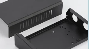
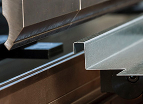
Custom sheet metal brackets need to do more than match a cutting profile. A mounting hole can be correct in the flat blank but sit in the wrong place after forming. A flange can face the wrong way, or a fixing can become inaccessible when the surrounding equipment is installed.
This guide helps engineers, maintenance teams and buyers define the drawing, bending and mounting requirements that determine whether a bracket fits. It focuses on installation-ready information rather than a general introduction to sheet metal fabrication.
Quick answer: Supply the finished bracket geometry, material and thickness, critical mounting faces and hole relationships, bend orientation, and quantity. Include mating-part details and tool-access constraints. Agree which dimensions and assembly checks must be accepted before releasing a production batch.
For buyers sourcing custom metal brackets in Singapore, the useful starting point is a coordinated review of sheet metal laser cutting and CNC bending and folding. The flat profile and formed interfaces should describe the same part revision.
Start With What the Bracket Must Connect
Identify the two components or surfaces the bracket connects. Show which face seats against the equipment, which features locate the attached component, and whether adjustment is required during installation. Add an assembly view when the bracket drawing alone cannot explain these relationships.
A simple shape name is not enough. Two L-shaped brackets may have different mounting directions, access restrictions and acceptance requirements despite sharing the same outline.
| Bracket arrangement | Information that matters for fit |
|---|---|
| L-shaped bracket | Leg lengths, included angle, mounting faces and the relationship between holes on different legs. |
| U-shaped bracket | Clear internal opening, side heights, inside bend geometry and opposing-hole alignment. |
| Z-shaped bracket | Offset between mounting faces, bend directions and clearance to adjacent components. |
| Left- and right-hand pair | Separate identifiers, unambiguous formed views and the quantity required of each hand. |
Include nearby cables, covers or moving components where they limit the available space. If the bracket is a replacement, photographs of the installed part can explain access constraints, but photographs alone do not establish reliable manufacturing dimensions.
Fit is not a load rating. A bracket that installs correctly has not necessarily been validated for its service loads. Load cases, fasteners, deflection, fatigue and safety requirements need appropriate engineering assessment. This guide does not establish structural capacity.
Dimension the Finished Bracket, Not Only the Flat Blank
A DXF profile describes cutting geometry. It does not, by itself, establish the final relationship between flanges after bending. The drawing or model needs to define the formed part, including the relevant angles, radii and dimensions between mounting features.
Distinguish internal dimensions from external dimensions. For a U-shaped part, outside width is not the same as the clear opening available to receive a mating component. Thickness, bend geometry and angular variation all affect the relationship.
Illustrative example: a U-bracket around a housing
Suppose a housing sits between two bracket legs and is fixed through side holes. The useful requirements include the available internal opening, hole locations relative to the seating surface, and clearance around the housing corners. An outside-width dimension alone leaves important installation questions unanswered.
Show the housing envelope or provide its mating drawing. Specify the intended clearance and relevant tolerances rather than asking the fabricator to infer them. This is a drawing example, not a customer case or a proposed tolerance for every U-bracket.
Use consistent reference features for critical dimensions. If the engineering drawing specifies datums or geometric tolerances, preserve that definition across revisions. State whether a fit-critical requirement applies before or after finishing, and clarify the measurement condition where clamping could change the result.
The separate CNC bending tolerance, K-factor and springback guide explains forming considerations. For procurement, the priority is to define the required finished geometry and agree who supplies or validates the manufacturing flat pattern.
Separate Mounting Holes, Locating Features and Adjustment Slots
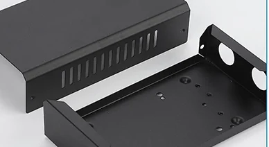
Not every opening performs the same job. A clearance hole allows a fastener to pass through; a locating feature controls position; a slot allows movement in a specified direction. Mark these functions where they affect manufacturing or inspection.
- Fastener clearance: identify the intended hardware and required clearance, including any finish allowance specified by the designer.
- Locating features: define the mating feature and required fit. Do not assume every laser-cut hole is suitable for a precision locating function without review.
- Adjustment slots: state the adjustment direction and usable travel, with enough information to check the fastener and washer arrangement.
- Access openings: explain whether the opening is for a tool, cable or component so that its functional boundary is understood.
Do not solve a hole-pattern conflict simply by enlarging the holes. A change may affect location, clamping or the surrounding material. Obtain design approval before altering a functional feature.
For features close to bends, review distortion risk and manufacturing access with the supplier. The sheet metal laser cutting design guide covers broader feature-design considerations; the bracket drawing should identify which dimensions must remain unchanged to preserve assembly fit.
Check Bend Direction, Tool Access and Left–Right Parts
Use formed views to remove ambiguity about bend direction. A flat view with an unexplained arrow can be interpreted incorrectly, especially for mirrored parts or brackets with several offsets. Identify the viewing direction and link every view to the same part number.
There are two different access checks. Manufacturing access concerns whether the proposed geometry can be formed using a suitable bend sequence and tooling. Installation access concerns whether the installer can insert and tighten the fasteners after neighbouring components are present.
For sheet metal mounting brackets, check the complete fastening sequence: bolt insertion, washer placement, nut retention and socket or spanner clearance. A bolt that fits through a hole does not prove that it can be tightened. Include the adjacent panel or equipment envelope in the review where it blocks access.
For left- and right-hand bent metal brackets, specify separate part identifiers and quantities. Do not rely only on a note saying “opposite hand” if asymmetric holes or finish requirements could be missed. Agree any identification marks and their permitted location without marking a protected appearance surface.
Specify Material, Finish and Protected Faces
Specify the material grade, thickness and relevant condition rather than only “steel” or “aluminium”. The material choice should reflect the design and service environment, while bend suitability needs review against the actual geometry. Do not assume a visually similar substitute behaves identically.
State the final finish and identify cosmetic faces, exposed edges and contact surfaces. Where required by the design, define areas that must remain uncoated or protected. Coatings on mating surfaces and inside openings can affect fit, so connect finish requirements to the critical dimensions.
Also define acceptable edge condition and packaging needs. For visible brackets, agree how appearance will be assessed instead of using an undefined “scratch-free” instruction. Protective separation during packing may matter when finished parts can rub against one another.
Agree First-Piece and Assembly Checks Before the Batch
A first-piece review is particularly useful for a new geometry, a revised mounting interface or a replacement part with uncertain mating dimensions. The extent of checking should match the project risk and be agreed during quotation; it is not automatically the same inspection package for every order.
- Confirm identity: correct part number, drawing revision, material and left/right hand.
- Check formed geometry: mounting faces, bend orientation, critical opening and offset dimensions.
- Check functional features: required hole sizes and locations, slots and specified locating fits.
- Confirm assembly where agreed: seating, mating-part clearance and installation-tool access.
- Review final condition: edges, finish, permitted marks and packaging before batch release.
Keep dimensional inspection separate from assembly confirmation. If the actual mating component or an agreed checking fixture is unavailable, inspection can verify the drawing requirements but cannot demonstrate every aspect of installation on the equipment.
Record any approved changes and update the released drawing. An adjustment accepted verbally on a sample can otherwise disappear from the next order. Retain the relevant revision and acceptance record for repeat production.
RFQ Checklist for Custom Sheet Metal Brackets
A clear RFQ makes it easier to assess cutting, bending, finishing and inspection together. Send the following information, marking unresolved items as questions rather than allowing assumptions to become manufacturing instructions.
- Part identity: name, part number, revision and quantities for each variant or hand.
- Material: grade, thickness, relevant condition and whether alternatives may be proposed.
- Geometry: a dimensioned PDF and a formed 3D model such as STEP where available; a DXF when required for the agreed cutting workflow.
- Mounting requirements: reference faces, critical dimensions, tolerances, mating drawings and adjustment needs.
- Finish and appearance: final finish, cosmetic faces, protected areas and edge requirements.
- Acceptance: first-piece needs, agreed assembly checks and any required inspection documentation.
- Delivery: quantity, target delivery date, packing requirements and delivery location.
If the model, PDF and flat pattern disagree, identify and resolve the conflict before production. Agree the controlling document rather than assuming the newest filename is authoritative. The CAD file preparation guide provides additional file-handover guidance.
Frequently Asked Questions
Is a DXF enough to order a bent bracket?
Usually not on its own. A cutting profile needs supporting information that defines material, thickness, formed geometry, bend orientation and acceptance requirements. Supply a dimensioned formed drawing and a 3D model where available.
Should a U-bracket be dimensioned inside or outside?
Define the dimension that controls its function and label it clearly. If a component fits between the legs, the internal opening is important. Other external and mounting dimensions may also be required; avoid conflicting or redundant tolerances.
Can slots compensate for installation variation?
They can provide intentional adjustment when the design permits it. Define the direction and travel and check the fastening arrangement. Adding slots is a design change, not a universal remedy for incorrect hole positions.
Do all bracket orders need a sample first?
Not necessarily. A new or uncertain interface may justify a sample or first-piece approval, while an unchanged repeat order may use an established acceptance plan. Agree the approach before batch production.
Can I request a quote using photographs of an existing bracket?
Photographs can support an initial discussion. Include overall dimensions, material information and views of the installed part. Reliable manufacturing still requires confirmed geometry and acceptance requirements; worn or distorted old parts need particular care.
Planning a Custom Sheet Metal Bracket?
Send your drawing or model, material and thickness, quantity, and critical mounting requirements. Include mating-part details where fit depends on another component, so the cutting and bending requirements can be reviewed together.