A coordinate measuring machine (CMM) measures a part in three dimensions by recording points on or near its surfaces and comparing the resulting geometry with drawing or CAD requirements. CMM inspection is especially useful for datum-based GD&T, hole patterns and complex relationships that are difficult to verify with hand tools. It is not automatically required for every precision part, and there is no universal “CMM accuracy”: the result depends on the machine specification, probing system, measuring length, environment, fixturing, datum strategy and inspection program.
For a buyer, the important question is not simply whether a supplier has a CMM. It is whether the selected inspection method can verify the drawing, whether the measurement result is fit for its intended use, and whether the report contains the information your quality team needs.
This guide explains what CMM inspection can measure, when a CMM report is worth requesting, how CMM compares with calipers and optical measurement, and what Singapore procurement teams should define before placing an order.
What Is a Coordinate Measuring Machine?
A CMM establishes an X, Y and Z coordinate system and records the position of measured points relative to that system. Inspection software uses those points to calculate geometric features such as planes, circles, cylinders and profiles, then compares the measured result with nominal dimensions and tolerances.
Depending on the machine and application, data may be collected with:
- Touch-trigger probing: records individual points when a stylus contacts the part.
- Scanning probing: collects many points while the stylus follows a surface.
- Optical or non-contact sensing: measures selected features that are small, flexible, delicate or unsuitable for contact.
- Multi-sensor systems: combine more than one sensing method when a part contains different feature types.
What Can CMM Inspection Measure?
CMM inspection is valuable when a drawing defines relationships between features rather than only simple lengths. Depending on equipment capability, feature accessibility and the inspection plan, a CMM may evaluate:
| Measurement group | Examples | Why a CMM may help |
|---|---|---|
| Size | Length, width, diameter, distance and angle | Creates a consistent coordinate-based measurement routine |
| Location | Hole centres, pattern positions and feature spacing | Relates multiple features to common drawing datums |
| Orientation | Parallelism, perpendicularity and angularity | Evaluates relationships between planes, axes and datums |
| Form | Flatness, straightness, circularity and cylindricity | Uses multiple points or scanning data to estimate geometric form |
| Profile and GD&T | Position, profile of a line or surface, concentric relationships | Supports datum-based analysis of complex geometry |
Not every feature is suitable for a CMM. Very thin flexible parts may move under contact; deep or obstructed features may be inaccessible; rough surfaces can affect probing; and specialised characteristics such as surface roughness, thread quality or material composition normally require other instruments.
CMM vs Calipers, Micrometers and Optical Measurement
The best inspection plan often combines several tools. Using a CMM for every dimension can increase programming and inspection cost without improving the decision, while relying only on hand tools can be inadequate for complex datum relationships.
| Inspection method | Good fit | Important limitation |
|---|---|---|
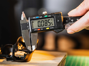
| Caliper | Fast checks of straightforward internal, external and step dimensions | Result can be sensitive to access, alignment, measuring force and operator technique |
| Micrometer | Thickness, outside diameter and other local one-axis dimensions | Limited for complex three-dimensional relationships |
| Height gauge and surface plate | Heights, steps and selected positional checks from a stable reference | Setup, datum simulation and access must be controlled |
| Optical comparator or vision system | Small two-dimensional profiles, thin parts and non-contact measurement | Depth and complex 3D relationships may require another method |
| CMM | Complex 3D geometry, datum structures, patterns and repeatable measurement programs | Requires suitable access, programming, fixturing and controlled measurement conditions |
| Go/no-go gauge | Fast pass/fail checks in stable, higher-volume production | Usually does not provide a complete numerical measurement result |
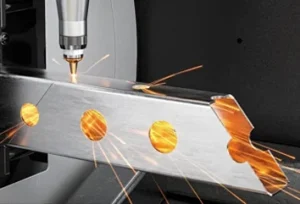
For laser-cut profiles, an optical method may be efficient for many two-dimensional features. For a bent or machined assembly with multiple datums and hole axes, a CMM may provide a clearer verification route. The drawing and intended function should drive the decision.
How Accurate Is CMM Inspection?
There is no universal accuracy value for CMM inspection. A machine may have a manufacturer-specified maximum permissible error, but the uncertainty of a specific part measurement also depends on measuring length, position in the measuring volume, probe configuration, temperature, fixturing, sampling strategy, software evaluation and part stability.
Resolution, repeatability, MPE and uncertainty are different
Before comparing CMM suppliers, separate the terms that are often compressed into the word “accuracy.”
| Term | What it tells you | What it does not tell you |
|---|---|---|
| Display resolution | The smallest increment the software or scale displays | Whether the system can measure accurately to that displayed digit |
| Repeatability | How closely repeated results agree under similar conditions | Whether those consistent results are close to the reference value |
| Maximum permissible error (MPE) | The equipment performance limit under specified acceptance or reverification conditions | The uncertainty of every feature measured on every part |
| Calibration result | Observed performance at tested positions, directions and lengths, including the calibration uncertainty | Automatic proof of every future measurement task |
| Measurement uncertainty | Quantified doubt associated with a specific measurement result | A generic catalogue specification for the machine |
| Drawing tolerance | The permitted variation of the workpiece characteristic | The capability of the selected measurement process |
A system can show excellent resolution and repeatability while producing a biased result. Conversely, a machine may meet its published MPE yet still be unsuitable for a particular measurement because of the part, probe, environment or program.
How to read a CMM MPE specification
The ISO 10360 series defines acceptance and reverification tests for coordinate measuring systems. Different tests apply to length measurement, single- and multi-stylus probing, scanning and other system configurations. ISO 10360-5 notes that probing performance is stated through maximum permissible errors because the probe cannot be practically isolated from the CMM during testing. See the official ISO 10360-5 overview.
A manufacturer may express the length measurement MPE in a form similar to:
| Illustrative measured length | Formula result | What the example shows |
|---|---|---|
| 100 mm | About 2.33 μm | The equipment limit changes with measurement length; one fixed ± value cannot describe every length. |
| 300 mm | About 3.00 μm | |
| 900 mm | About 5.00 μm |
Real specifications also state the applicable temperature range, probe configuration, measuring mode and test standard. For example, published ZEISS CMM specifications and Hexagon guidance on shop-floor CMM accuracy show length-dependent MPE values and defined environmental conditions. The value should therefore be read together with all its qualifiers—not copied into a quotation as an unconditional part-measurement guarantee.
Nine factors that influence an actual CMM result
1. Machine specification and test condition
Identify the CMM brand, model, measuring volume and applicable ISO 10360 performance figures. Ask whether the claimed value describes length measurement, probing or scanning, and verify the temperature and configuration to which it applies.
2. Measurement length
The length-dependent term in an MPE formula means that a short feature and a long dimension cannot automatically be assigned the same equipment limit. A capability statement should be evaluated at the approximate length relevant to the part.
3. Position and direction in the measuring volume
Parts can be measured along an axis, across several axes or on a spatial diagonal. The part may also sit near the centre or edge of the measuring volume. Calibration at one location and orientation does not mean every position, direction and feature will produce an identical result.
4. Probe and stylus configuration
Touch-trigger and scanning probes have different performance characteristics. Stylus length, extensions, joints, ball diameter, ball form, probe angle, contact force and qualification all matter. A long or complex stylus arrangement can be necessary for access while also increasing deflection and sensitivity. ZEISS lists the stylus, fixture, temperature, measuring program and machine among the influences on measurement accuracy in its CMM stylus guidance.
5. Temperature and thermal gradients
The machine, part and reference artefacts must be considered together. A part brought directly from machining may not be at the same temperature as the measuring room. Material expansion, incorrect thermal expansion coefficients, rapid temperature change and gradients across a large part can all influence the result—even when software applies temperature compensation.
As an order-of-magnitude illustration, a 500 mm steel part can change by several micrometres for a temperature change of only 1°C. The exact change depends on the material and its coefficient of thermal expansion. Therefore “measured in an air-conditioned room” is not a complete environmental specification.
6. Measurement strategy and software evaluation
The operator or program determines how many points are taken, where those points are placed, the approach direction, scanning speed, filtering, datum construction and fitting algorithm. A mathematical plane can be created from three points, but three points cannot describe all the form variation of a real surface.
NIST guidance identifies sampling strategy, fitting algorithm, part location, operating parameters and probe approach among the sources that can materially affect a CMM result. See NISTIR 5170 on CMM measurement uncertainty.
7. Part stability and fixturing
Thin sheet, plastic, elastomeric or flexible parts may move under probing force. Heavy parts can deform under their own weight, while excessive clamping can distort a component into a condition that does not represent its functional state. Burrs, dirt, surface roughness, coating and residual heat can also affect contact and alignment.
8. Calibration, reverification and traceability
“Calibrated” should lead to further questions: When was the CMM tested? Which performance characteristics and configurations were covered? What were the observed results and test uncertainty? Is the calibration appropriately traceable for the project? What interim checks are performed after maintenance, movement or a suspected collision?
A fixed annual interval is not automatically correct for every system. The interval and interim verification should reflect use, stability, environmental conditions, risk and applicable customer or quality-system requirements.
9. Task-specific measurement uncertainty
The measurement uncertainty of a particular feature includes more than the catalogue MPE. It can include the machine, probe, environment, part, fixturing, sampling strategy, software evaluation and repeatability of the complete measurement procedure.
The ISO 15530 series covers methods for evaluating CMM measurement uncertainty, including the use of calibrated workpieces or standards and simulation-based evaluation. See ISO 15530-3 and ISO/TS 15530-4. This is why the following quantities should not be treated as interchangeable:
Can the CMM reliably verify the drawing tolerance?
For a buyer, the practical question is not “How many decimal places can the CMM display?” It is whether the complete measurement process can support a reliable conformity decision for the specified characteristic.
That decision depends on:
- the upper and lower specification limits;
- the task-specific measurement uncertainty;
- the measured value’s distance from the tolerance boundary;
- the agreed acceptance or decision rule; and
- the risk of accepting a nonconforming part or rejecting a conforming part.
ISO 14253-1 establishes decision rules for assessing conformity or nonconformity while taking measurement uncertainty into account. When a result is close to a specification limit, software displaying “PASS” does not by itself explain the decision rule or the risk associated with the uncertainty. See the ISO 14253-1 overview.
Do not apply a universal 4:1 or 10:1 ratio to every order without context. Such ratios may be used as internal policies, but the appropriate capability and decision rule depend on the project, customer and applicable standard.
CMM accuracy questions to ask before ordering
- What is the CMM brand, model and usable measuring volume?
- Which ISO 10360 MPE specification applies?
- What is the MPE at the approximate length of my critical feature?
- Which probe, stylus and measuring mode will be used?
- Can the selected configuration access every critical feature?
- What temperature range and stability conditions apply?
- How will the part be supported, stabilised and aligned?
- How many points or scan paths will define each important feature?
- Which datum construction and fitting method will be used?
- Is calibration current and appropriately traceable?
- Is a task-specific uncertainty statement required?
- Which decision rule applies near a tolerance limit?
- Can a sample report be reviewed before the order?
When Should a Buyer Request a CMM Report?
A CMM report is most useful when it resolves a defined inspection risk. Consider requesting it when:
- the drawing contains complex datum-based GD&T;
- multiple holes, planes or axes must be related in three dimensions;
- critical assembly interfaces are difficult to verify with hand tools;
- a customer contract or approved quality plan specifies CMM data;
- a first article, engineering change or process transfer needs structured dimensional evidence; or
- measurement data must be retained for review or traceability.
CMM inspection may not be the most economical choice for a small set of simple dimensions, for characteristics that can be controlled reliably with a dedicated gauge, or when another instrument is better suited to the feature. A ±0.05 mm tolerance by itself does not prove that CMM measurement is necessary.
Define the scope before quotation
“CMM report required” is not enough detail for an accurate quotation. Specify whether the requirement covers every drawing characteristic, only marked critical features, one first article, a sample from each batch or every part. Programming, setup, measurement time, review and document preparation all affect cost and lead time.
What Should a Useful CMM Report Include?
Report formats differ, so buyers should agree the required output before production. Depending on the project, a useful dimensional report may include:
- customer part number and drawing revision;
- part, serial, lot or batch identification;
- inspection date and approval information;
- measurement equipment and program identification;
- probe configuration and datum alignment;
- balloon or characteristic number;
- nominal value, upper and lower limits;
- actual value, deviation and pass/fail result;
- units and any relevant measurement notes; and
- calibration, environmental or uncertainty information when contractually required.
A long printout is not necessarily a complete report. It should be possible to connect each result to the correct drawing feature, revision, inspected part and acceptance decision.
Is a CMM Report the Same as a First Article Inspection?
No. A CMM report is measurement output from a coordinate measuring system. A first article inspection (FAI) is a defined verification activity used to show that a production process can produce characteristics required by the applicable design record. CMM data may support an FAI, but it is only one possible part of the evidence.
An FAI package may also reference material records, process documents, drawing revisions, inspection results obtained with other instruments and customer-specific forms. IAQG 9102 provides a standardised FAI framework for aviation, space and defence organisations; it should not be described as a universal requirement for all precision-manufacturing orders.
CMM Inspection for Precision Parts in Singapore
Singapore buyers frequently coordinate design, manufacturing, inspection and assembly across more than one facility. When CMM data is required, confirm during RFQ review whether the inspection is performed by the manufacturer or an external laboratory, where it will be completed, and how transport, programming and reporting affect the delivery schedule.
For semiconductor equipment, industrial automation, medtech and other precision-engineering projects, inspection requirements should be based on the drawing, customer specification, contract and risk assessment—not on a blanket claim that one industry always requires CMM inspection. See our application pages for semiconductor and electronics components and industrial automation parts.
Where traceability is required, ask how calibration is linked to appropriate measurement standards. In Singapore, the A*STAR National Metrology Centre is the national measurement institute and provides measurement and calibration capabilities traceable to the International System of Units. This does not mean every project requires national-laboratory calibration; the appropriate chain should be defined by the applicable specification and intended use.
Questions to ask a Singapore supplier
- Is the proposed inspection performed in-house or by an external provider?
- Which equipment and measuring volume will be used?
- Can the selected method access and measure every critical feature?
- What report format and characteristic coverage are included in the quotation?
- Does external inspection add transport, setup or queue time?
- What drawing, CAD and datum information is needed before programming?
- What calibration or traceability evidence is available when the contract requires it?
For Lumen Future projects, review the currently published quality assurance and dimensional inspection approach. If your drawing specifically requires CMM data, identify the characteristics and reporting standard during quotation so the appropriate inspection route can be evaluated before an order is accepted.
CMM Inspection RFQ Checklist
| Provide | Why it matters |
|---|---|
| Controlled 2D drawing and revision | Defines dimensions, tolerances, datums, notes and acceptance criteria |
| STEP or other suitable 3D model | Supports feature review and offline programming where applicable |
| Critical-characteristic list | Prevents unnecessary full-layout inspection and focuses the report |
| Sampling plan | Clarifies whether inspection applies to a first article, batch sample or every part |
| Required report format | Separates a basic dimensional report from CMM output, FAI or customer forms |
| Traceability requirement | Defines part identification, retention and calibration evidence before quotation |
For file preparation, see our CAD file preparation guide and the comparison of STEP, IGES and DXF files.
Frequently Asked Questions
Is CMM inspection required for every precision part?
No. The appropriate method depends on the feature, tolerance, geometry, reporting requirement and risk. Calipers, micrometers, height gauges, optical systems, dedicated gauges and specialised instruments may be more suitable for some characteristics.
How accurate is a CMM?
Accuracy is specific to the machine, measuring length, probe, environment and measurement strategy. Review the applicable manufacturer specification, calibration status and measurement uncertainty required for the decision rather than relying on a generic ± value.
Is CMM accuracy the same as display resolution?
No. Resolution is the smallest increment displayed by the system. It does not prove that the result is accurate to that increment. A CMM displaying 1 μm—or a smaller value—cannot automatically be described as measuring accurately to ±1 μm; the applicable MPE, probe, environment, strategy, part condition and task-specific uncertainty must also be considered.
Is a CMM report the same as an FAI report?
No. CMM output contains measurement results. FAI is a broader verification activity and may include CMM data, measurements from other tools, material records, process information and customer-specific documentation.
Is CMM always better than optical measurement?
No. A vision or optical system may be better for small, thin, flexible or two-dimensional features, while a CMM can be advantageous for complex three-dimensional and datum-based relationships. Some parts require both methods.
Can CMM inspection be arranged for a Singapore project?
Availability and scope should be confirmed during quotation. Provide the drawing, critical features, sampling requirement and report format so the supplier can evaluate whether the work should be measured internally, externally or with another suitable inspection method.
Does ISO 9001 require every CMM to be calibrated annually?
ISO 9001 does not impose one universal annual interval for every measuring instrument. When measurement traceability is a requirement or is considered essential to confidence in the result, equipment must be appropriately calibrated or verified, identified and protected. The method and interval should reflect intended use, risk and applicable requirements; see the ISO 9001 Auditing Practices Group guidance on measurement traceability.
Plan the Inspection Before Production
The most useful inspection plan starts with the drawing and the assembly risk. Define the critical characteristics, datum scheme, sampling level and required documents before comparing quotations. This gives the manufacturer time to select a suitable measurement method and avoids discovering after production that the report does not match your customer’s expectations.
Need a dimensional inspection plan for your parts?
Send the controlled drawing, CAD file, quantity, critical features and required report format. Lumen Future can review the manufacturing and inspection requirements and clarify the proposed route before quotation.