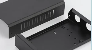
A bracket can meet its cutting dimensions and still miss its mounting points after welding. An enclosure can appear square in a fixture but change shape when released. For laser-welded sheet metal assemblies, the acceptance requirement needs to describe the finished component, not just the individual blanks.
Quick answer: Define the assembly reference features, critical interfaces, weld requirements and measurement condition before production. Review joint fit-up after forming, then agree the checks needed after welding and finishing. Low-distortion welding is not a guarantee of zero movement or a universal finished-part tolerance.
This guide is for engineers and buyers preparing light sheet metal assemblies, brackets and equipment housings for quotation. Lumen Future’s laser welding service in Singapore focuses on precision metal parts and light assemblies. It is not positioned as general TIG, MIG or heavy structural welding.
Fit-Up and Final Assembly Fit Are Different
Fit-up describes how the parts meet before welding: the joint gap, edge mismatch, angle and relative location. Final assembly fit describes whether the welded component interfaces correctly with its mating equipment. Both need attention, but they are not interchangeable.
Consider a formed cover with welded corner seams and mounting holes. Before welding, the corners must meet in the intended position. After welding, the opening and hole pattern still need to align with the equipment. A satisfactory corner joint alone does not prove that the completed cover will fit.
This is an illustrative example, not a customer case or a statement of achievable tolerance. The drawing must define the actual interfaces and permitted variation for the project.
Why Cutting Tolerance Is Not a Welded-Assembly Tolerance
Cutting controls the flat profile and features. Forming establishes angles and flange locations. Assembly introduces relationships between separate parts, while welding adds local heating and contraction. A tolerance on the blank does not automatically control the final position of a feature on the assembled part.
Incoming geometry also matters. If a flange is outside its forming requirement, pulling it into place may conceal the discrepancy during setup. Record what has been checked before welding rather than assuming the fixture will correct every earlier variation.
For problems already present in flat blanks, see the sheet metal flatness after laser cutting guide. Keep those checks distinct from inspection of the completed weldment so that the source of a dimensional issue can be investigated.
Mark the Interfaces That Determine Whether the Part Fits
Start with the assembly drawing. Identify the surface that seats against the equipment, the mounting-hole pattern and any opening or flange that must match another component. Show how these features relate to the specified references.
| Functional feature | What the drawing should establish |
|---|---|
| Mounting-hole group | Location relative to the assembly references, mating hardware and applicable size and position requirements. |
| Mounting face | The contacting surface, required geometry and support or restraint condition for inspection. |
| Enclosure opening | Required dimensions, orientation and relationship to the mating panel or frame. |
| Bracket ears or flanges | Relative position, angle and the interface that controls installation. |
Distinguish individual-part dimensions from assembly dimensions. Identify handed parts and viewing directions. If the drawing uses a formal datum system or geometric tolerances, retain that definition rather than replacing it with informal instructions such as “keep square”.
Diagonal measurements can support an agreed check of a frame, but do not establish every angle, surface condition or three-dimensional relationship. Likewise, passing a bolt through a hole is not a substitute for a specified positional inspection.
Aim for requirements that reflect function. Applying the tightest tolerance to every edge can increase inspection and manufacturing effort without improving the interfaces that matter.
Review Joint Fit-Up After Cutting and Bending
Provide an assembly view as well as flat cutting files. A useful review considers the joint in its formed condition, with neighbouring flanges and fixture contact points present.
- Gap: is the intended joint opening defined and repeatable along the seam?
- Mismatch: do adjoining edges meet at the required level and angle?
- Access: can the proposed welding setup reach the complete path?
- Surface condition: are coatings, oxide or residue identified for process review?
- Support: can the part be located without obstructing the seam or damaging a cosmetic surface?
- Variation: will the arrangement accommodate the agreed incoming-part variation?
There is no single acceptable laser-welding gap for every material, thickness and joint. Suitability depends on the process arrangement and required weld performance. Send the actual joint geometry for review instead of copying a gap from an unrelated demonstration.
If preparation is needed, define the areas and required condition. Do not assume cleaning can correct an unsuitable joint shape, edge mismatch or missing material.
What Fixtures and Welding Sequence Can Control
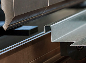
Locating establishes where the parts sit; clamping holds them during the operation. The arrangement must also allow access to the weld path and removal of the finished component. These are separate requirements, not simply a question of applying more clamping force.
Restraint can influence distortion, but a component held to shape during welding may move when released. TWI’s guidance on pre-setting and restraint describes the need to consider assembly geometry, complexity and residual stresses when selecting a control method. It is general technical guidance, not a statement of Lumen Future’s equipment or project capability.
The welding sequence should be reviewed with joint layout, access and the inspection plan. Do not prescribe a universal sequence, preset amount or correction method from an example drawing. Any trial should represent the intended material, joint and assembly conditions.
Do not change the weld design simply to reduce visible movement. Weld size, length, location and continuity must satisfy the approved design and applicable requirements. Changes need appropriate approval; they are not routine substitutions for the supplier to make without agreement.
Agree the fixture scope at quotation, including any customer-supplied tooling. A request for a welded component does not automatically include a dedicated fixture design or a particular automated positioning system.
Decide When Critical Holes and Faces Are Finished
Some features can be completed before welding. Others may need a later operation because their final relationship is controlled by the assembled component. This is a planning decision, not a reason to defer every hole until after welding.
For a critical interface, identify the final reference, required tolerance and inspection method. Review whether the chosen sequence can meet that requirement. Where post-weld machining is needed, confirm access, locating surfaces, allowance and the supply scope before quotation.
A hole can meet its diameter requirement before welding while its position relative to another part changes afterwards. The laser-cut hole quality guide explains why hole quality and downstream finishing need separate consideration.
Do not assume Lumen Future will automatically machine every weldment or correct an unsuitable design. Any additional operation must be confirmed for the actual component and included in the agreed route.
Inspect at Defined Stages and in a Defined Condition
“Check after welding” is incomplete if one party measures in a fixture and another measures the part unsupported. State whether acceptance applies in a free state, on specified supports or in a defined installed condition. For flexible sheet metal, the support arrangement can be important to interpreting a measurement.
| Stage | Purpose of the agreed check |
|---|---|
| After cutting and forming | Confirm incoming features and conditions needed for fit-up. |
| During assembly setup | Confirm orientation, joint arrangement and critical relative locations. |
| After welding | Check assembly geometry after the agreed cooling and fixture-release steps, in the specified measurement condition. |
| After finishing | Check final appearance and any interfaces or dimensions requiring reinspection. |
Define the measurement method and record requirements where they affect acceptance. A photograph can document orientation or appearance, but is not automatically evidence that a close dimensional tolerance has been met.
Keep three questions separate: does the weld meet its specified acceptance criteria, does the component meet its dimensional requirements, and does the assembly satisfy any functional test? A neat seam does not establish internal weld quality, strength or leak-tightness.
If the project requires procedure qualifications, inspection qualifications, non-destructive testing, leak testing or specific records, identify them before quotation. Their availability and scope must be confirmed rather than inferred from a general service description. See quality assurance when preparing the project inspection requirements.
Include Finishing and First-Article Requirements Early
Specify which welds remain visible and whether any dressing, brushing, polishing or coating is required. Identify mounting faces, threads and other features that need protection or masking. State whether the acceptance dimensions apply before or after the final treatment.
Grinding is not an automatic cure for a dimensional problem, and appearance requirements must not authorise uncontrolled removal of weld metal. Agree the permitted finish and retained weld requirements together.
For a new assembly, define what the first article must prove: drawing revision, material, fit-up, final interfaces, weld acceptance and appearance. Record any approved changes before releasing the batch. A successful sample does not by itself validate every future variation or establish certification for a safety-related product.
For repeat orders, identify the approved drawing, finishing specification and inspection arrangement. Changes to material, geometry, tooling or process should be reviewed for their effect on the previous approval.
RFQ Checklist for Laser-Welded Sheet Metal Assemblies
For a Singapore fabrication enquiry, submit a coordinated file pack rather than separate cutting drawings without an assembly definition:
- Assembly PDF and STEP model, with units, revision and part identification.
- Individual-part drawings or cutting files and a matching bill of materials.
- Material grades, thicknesses and the condition of any customer-supplied parts.
- Weld locations and the design requirements, including any applicable specification.
- Critical interfaces, tolerances, references and measurement condition.
- Weld appearance, inspection, testing and documentation requirements.
- Any proposed post-weld machining and final surface treatment.
- Prototype and batch quantities, variants and first-article approval requirements.
- Required delivery date, Singapore delivery location and packing or receiving constraints.
Request a clear statement of what is included: fabrication, fixture preparation where applicable, finishing, agreed inspection and delivery. Flag requirements that are still undecided so they can be resolved before production, rather than becoming an acceptance dispute afterwards.
Frequently Asked Questions
Does laser welding eliminate sheet metal distortion?
No. It can be considered where controlled heat input and narrow seams are useful, but final movement depends on the joint, material, geometry and manufacturing arrangement. Agree the finished-component requirement and verification method for the project.
Can the same tolerance be used for a blank and the welded assembly?
Not automatically. A blank dimension and an assembly interface describe different requirements. Define each on the relevant drawing and confirm that the proposed process can meet them.
Should dimensions be checked while the part is clamped?
Only where that is the specified inspection condition. A fixture check can support process control, but final acceptance should use the agreed free, supported or installed condition.
Can you quote from DXF files alone?
DXF files may describe the flat parts but usually do not fully define a welded assembly. Add an assembly drawing or model, material information, weld requirements and critical fit details for review.
Send Your Assembly Drawing for Review
Share the material, quantity, weld locations and critical fit requirements. Include the final finish and inspection condition so the laser-welding route and supply scope can be reviewed before quotation.