

A laser-cut aluminium blank can match its flat drawing and still become a poor equipment panel. A tight bend may show a crack on its outside face; a hole pattern may no longer line up after forming; or a good-looking cover may block access to its mounting screws. For bent aluminium equipment panels, the useful question is whether the finished, installed part meets its function.
This guide is for equipment builders, system integrators and maintenance buyers preparing an enquiry for solid-sheet aluminium covers and access panels in Singapore.
Quick answer: Before ordering, specify the exact aluminium alloy and temper, sheet thickness, bend geometry, panel orientation and the dimensions that must be correct after bending. Identify mounting datums, mating parts, visible faces and any finishing requirement. For a new or replacement panel with a critical fit, agree how the first formed part will be checked before the remaining quantity is made.
In this guide
Define the Panel’s Job Before Reviewing Its Bends
Start with where the panel sits and how it will be used. Is it a fixed equipment cover, a removable maintenance panel, or a front plate with controls and openings? Which surface meets the frame, and from which direction will a technician insert the fasteners? A drawing of the panel alone may not show the adjacent hinge, cable, bracket or tool clearance that determines whether it can be installed.
| Project question | Show or state in the enquiry | Why it matters after bending |
|---|---|---|
| What locates the panel? | Frame contact face, locating edge or feature, and mating hole pattern. | Overall width alone does not establish installed alignment. |
| What must remain accessible? | Fastener approach, door or cover opening direction, adjacent components and service clearance. | A flange can obstruct the tool or interfere with another part. |
| Which face is visible? | Cosmetic face, viewing direction, permitted handling marks and finish. | The bend tooling and handling route can affect the delivered appearance. |
Assess Bend-Crack Risk by Material and Geometry
“Aluminium” is not a complete bending specification. State the alloy and temper—such as 5052-H32 or 6061-T6—together with thickness. The site’s aluminium material guide and 5052 versus 6061 comparison cover grade selection; this checklist focuses on the finished panel.
Review the proposed inside radius, bend angle, flange length, rolling direction and any cutout or relief near the bend. The Aluminum Association’s design FAQ states that the radius needed to avoid cracking depends on alloy, temper, thickness, orientation to the grain and bend angle. There is therefore no single safe “1× thickness” or “1.5× thickness” rule for every aluminium equipment panel.
Show the bend direction and, if known, the sheet’s rolling direction on the drawing. Have the specified alloy-temper and tooling route checked before approving a tight bend. Consider a trial or first-off part when cracking, appearance or fit remains uncertain.
Replacing a cracked panel? Show the whole part, both sides of the bend, a crack close-up and the installed mounting. Record when the mark appeared. A metal crack and cracking of an anodised layer are different observations; do not copy the old material or bend radius without review.
Dimension Mounting Features on the Finished Panel
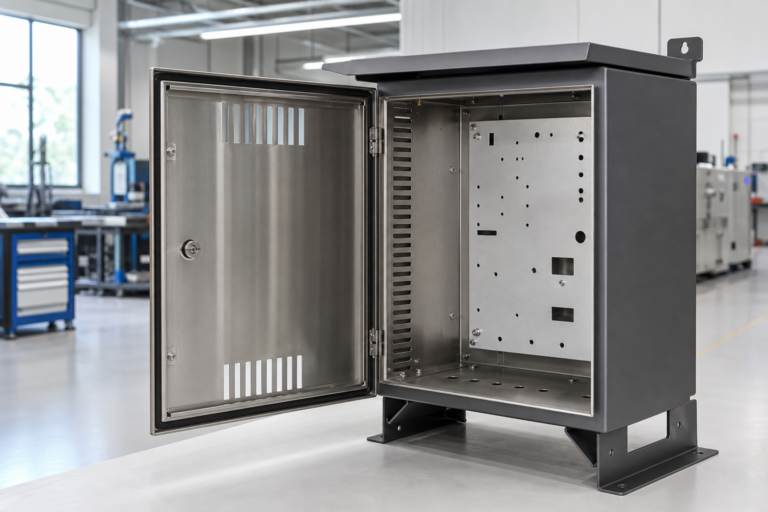
A flat DXF tells a cutting machine where to create a hole, but it does not fully define where that hole must sit relative to the equipment after the flange has been formed. Choose a stable installed reference—such as the rear seating face, a locating edge or an agreed pair of mounting features—and dimension the critical hole or slot positions from it on the folded drawing.
Separate functional mounting dimensions from general outer-envelope dimensions. Note which holes locate the panel and which provide clearance; show the mating frame’s hole pattern and the fastener approach. If a hole, slot or large opening is close to a bend, flag it for manufacturability review and specify the finished feature that matters. Nearby features can distort during forming, but there is no universal hole-to-bend clearance for every material and tool. See the hole and slot design guide for general cutting considerations.
Illustrative example: A U-shaped aluminium cover has four holes in two return flanges. Each hole is correctly cut in the flat blank, but one formed flange ends up at a different angle from the approved model. The cover then needs force to bolt onto the machine. The purchase drawing should control the final flange relationship and mounting-hole positions relative to the agreed seating face, not only the flat-pattern hole coordinates.
For a replacement panel, include photographs and dimensions of the old part, but identify dents, wear, previous rework or distortion. If the existing machine or a mating part controls fit, say whether a physical sample can be supplied and who will approve the first-piece trial. Do not assume that copying every measurement from a damaged old panel will recreate the intended fit.
Send a Drawing Package That Describes Both Flat and Formed States
The most useful reference is a controlled, dimensioned PDF of the finished folded panel, supported by a 3D STEP model where available. A flat DXF can assist cutting and bend planning, but it should not silently replace the approved final geometry. Keep drawing numbers, revisions, units and orientation consistent across all files; if they disagree, identify which released document governs.
| Item | What to provide | Acceptance question |
|---|---|---|
| Material and surface | Exact alloy, temper, sheet thickness, stock condition and required finish. | Is the proposed bend and appearance route suitable for this material? |
| Finished part PDF and STEP | Orientation, inside radii, bend angles, flange lengths, reliefs, datums and critical post-bend dimensions. | Will the formed part match the equipment interface? |
| Flat DXF, if supplied | Outline, holes, cutouts, bend lines and clear revision identification. | Can the blank be prepared without confusing it with the final inspection drawing? |
| Mating information | Machine-frame sketch or model, adjacent parts, mounting method and tool access. | Can the panel actually be installed and removed? |
| Inspection notes | Critical features, specified tolerances, visual face, first-off approval and measurement condition. | What exactly must pass before the order proceeds? |
Agree Appearance, Finishing and First-Off Checks
Mark the visible face and the surfaces that must remain free of unacceptable contact marks. Define the appearance standard using an agreed sample or written acceptance criteria rather than an unqualified “perfect finish”. State whether protective film, face identification or individual packing is needed. If the panel will be anodised or coated, specify whether critical dimensions and mounting fit are accepted before or after that operation.
Forming is generally planned before anodising because an anodic layer has limited ability to stretch; bending an already anodised surface may crack its coating. If pre-anodised sheet is specified, agree a trial and the acceptable appearance. See Hydro’s anodising guidance.
| Stage | Check to agree | Decision |
|---|---|---|
| Flat blank | Material identification, revision, outline, holes and cut-edge condition. | Is the correct blank ready to form? |
| After bending | Outside-bend surface, angle, flange geometry, finished hole pattern and agreed cosmetic faces. | Does the formed panel meet its drawing? |
| After finishing, if specified | Appearance and coating-affected interfaces or dimensions. | Is the delivered condition acceptable? |
| First-piece fit, if required | Trial against the agreed mating part or customer fixture before further production. | Can the remaining quantity proceed? |
Agree the acceptance values, method and sample quantity before production. The quality assurance page describes the site’s general inspection approach; specify any project-specific record or trial fit in the enquiry.
Bent Aluminium Equipment Panel RFQ Checklist for Singapore Projects
To request a practical review, send:
- A controlled finished-panel PDF and STEP model where available, with dimensions in mm and the current drawing revision.
- A flat DXF if available, clearly identified as a flat pattern rather than the sole acceptance drawing.
- The exact aluminium alloy, temper and sheet thickness.
- Bend direction, inside radius or space constraints, angle, flange dimensions and rolling direction if known.
- Installed orientation, mating-frame information, locating face and critical finished hole or slot pattern.
- Photographs or a physical old panel for a replacement, with damage clearly identified.
- Visible face, surface finish and any first-off fit or appearance check.
- Panel quantity and required delivery location in Singapore.
If information is missing, identify the unknowns so the drawing and bending route can be reviewed before quotation.
Frequently Asked Questions
Can 6061-T6 be used for a bent equipment panel?
It may be possible for a particular design, but a tight bend in this temper needs careful review. The answer depends on thickness, bend geometry, orientation, required function and the proposed manufacturing route. Do not substitute it for 5052 solely because both materials are labelled aluminium.
Which dimensions should be checked after bending?
Check the dimensions that determine installation: mating face or edge, critical flange relationship, hole and slot positions, clearances, orientation and any agreed overall envelope. Identify the reference datums and acceptance values on the finished-part drawing.
Is a flat DXF enough to order a fitted panel?
Usually not when formed geometry or mounting fit is important. Add a dimensioned folded-part PDF and, where available, a STEP model showing bend direction, final radii, datums and critical post-bend relationships.
Does a visible mark on an old bend prove the aluminium itself cracked?
No. A mark may be in the metal, a coating or an anodised layer. Record when it appeared and provide close photographs plus material and finishing information. Assess the replacement design rather than assuming the photograph alone establishes a cause.
Can a replacement panel be quoted from photographs only?
Photographs help explain orientation and damage, but critical mounting dimensions still need confirmation. Supply the existing drawing, measurements, mating-part information or a physical sample where possible; agree how the first-piece fit will be approved.
Send Your Aluminium Panel Drawing
For a Singapore equipment-panel enquiry, share the finished-part drawing, alloy and temper, thickness, quantity and the mounting features that must fit after bending. Add photos or a sample for a replacement, plus any finish or first-off requirement. We will review the cutting and CNC bending scope against the information supplied before quotation.