Sheet metal flatness after laser cutting is a separate quality requirement from length, width and hole position. A part can meet its linear dimensions yet rock on an assembly surface, lift at a corner or curve along a narrow section. Finding the cause requires looking beyond the laser alone.
Quick answer
Flatness after laser cutting depends on the incoming sheet, residual stress, local heat, remaining part stiffness, cut sequence, handling and later fabrication. The original sheet may already contain shape deviation or locked-in stress from rolling, levelling, slitting or previous processing. Cutting removes material and changes restraint, so pre-existing stress can redistribute even when the thermal input is relatively localised.
If flatness affects sealing, automation assembly, welding fit-up or equipment alignment, identify the controlled surface, tolerance, inspection stage and free or restrained condition on the drawing. For project-specific DFM, see our sheet metal laser cutting service in Singapore.
What Does Flatness Mean for a Laser-Cut Part?
Flatness describes the form of a surface. In geometric tolerancing, the evaluated surface must remain within a defined zone between two parallel planes. It is not the same as checking whether the overall length and width match a DXF file.
ISO 1101 establishes the symbolic language for geometric product specifications, while ISO 12781 covers flatness terminology and parameters. A production drawing may apply a flatness control to a selected surface without using another surface as a datum. If the real design need is a relationship to an assembly face, however, parallelism, profile, dimensional controls or a functional assembly requirement may also be needed.
Why Can a Dimensionally Correct Part Still Be Unflat?
Linear size and surface form answer different questions. Length, width and hole coordinates may all be within tolerance while the surface between those features curves or twists. This distinction becomes important when a panel supports linear guides, seals against a frame, carries sensors or must align with another fabricated component.
| Requirement | What it controls | What it does not prove |
|---|---|---|
| Length and width | Overall linear size | That the complete surface is flat |
| Hole diameter | Size of a circular opening | Part flatness or hole-pattern location |
| Hole position | Location relative to stated datums | Form of the surrounding sheet surface |
| Straightness | Form of a line or linear feature | Form of the entire surface |
| Parallelism | Orientation relative to a datum | Independent surface form unless also controlled |
| Flatness | Form of the selected surface | How a flexible part behaves under unspecified clamping |
The lesson for buyers is simple: a normal dimensional tolerance does not automatically create a flatness requirement. If rocking, sealing, contact or alignment matters, state it directly. Our laser cutting tolerance guide explains how to separate critical dimensions from general tolerances.
Six Sources of Sheet Metal Warping After Laser Cutting
1. Incoming sheet condition
The sheet may contain coil set, edge wave, centre buckle, local dents or handling damage before cutting begins. Material standards and supplier tolerances describe the incoming product under specified conditions; they do not automatically guarantee the flatness of every finished geometry cut from that product.
Inspecting the parent sheet is especially useful when multiple parts from the same location move in a similar direction, or when the same program behaves differently across material lots.
2. Residual stress in the material
Rolling, levelling, slitting, heat treatment, cold work and earlier manufacturing can leave non-uniform residual stress. A complete sheet may appear relatively stable because surrounding material restrains it. Once contours, slots or large internal areas are removed, that restraint changes and the stress can redistribute.
This means movement observed after cutting does not prove that laser heat created all of the distortion. Cutting may reveal or release stress that existed beforehand. SSAB publishes separate before- and after-cutting flatness guarantees for a specific laser-processing steel, illustrating why the two states should not be assumed identical. Those product-specific values must not be applied to ordinary sheet or to a different supplier’s material.
3. Localised laser heat
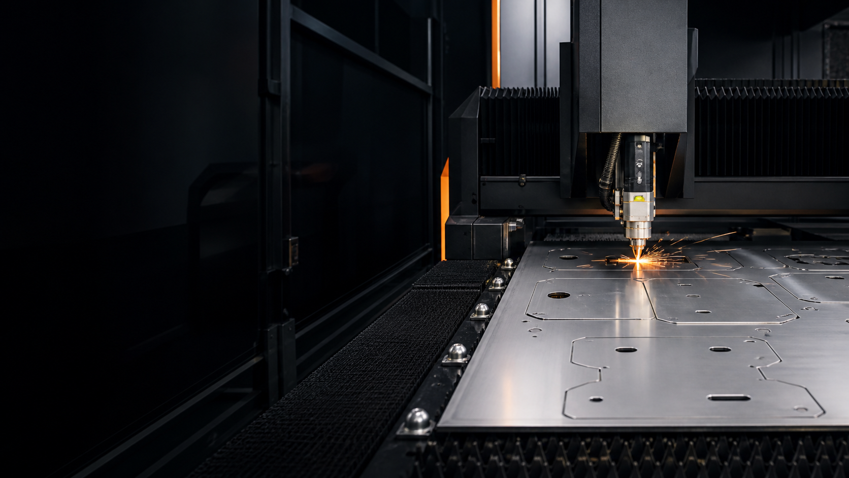
Laser cutting is a localised thermal process. The heated zone expands and then contracts as it cools. Dense perforations, prolonged piercing, an unfavourable sequence, slow cutting conditions or excessive heat in a low-stiffness area can contribute to distortion.
TWI describes laser cutting as a low-heat-input, low-distortion process. That is a relative process advantage, not a promise of zero distortion. Thin, large or flexible parts can still move when thermal input, stress and geometry combine unfavourably.
4. Geometry and loss of stiffness
Cutting changes the structural behaviour of the part. A solid rectangle, open frame, narrow strip and highly perforated panel cut from the same sheet will not retain the same stiffness. Risk often increases with long narrow geometry, thin large panels, asymmetric material removal, large openings, narrow bridges and abrupt section changes.
Two parts from the same sheet can therefore respond differently even when the machine program and material thickness are identical.
5. Unloading, handling and storage
A satisfactory part can be deformed after cutting by lifting it from one point, stacking it before it stabilises, storing a wide panel vertically, placing it on an uneven pallet or loading heavier items on top. Packaging and Singapore delivery should maintain suitable support for large or flexible components.
6. Bending, welding and later processing
Flatness measured immediately after cutting is not the same as final assembly form. Bending introduces intentional deformation and springback. Welding produces local heating, contraction and restraint. Grinding, press-fitting, coating cure and assembly clamping can also change the result. Acceptance must identify the stage at which it applies.
Diagnosing Distortion by the Observed Shape
The shape of the problem can guide investigation, but it rarely proves one cause by itself. Record the material lot, sheet position, nest orientation, cut sequence and inspection condition before changing the process.
| Observed condition | Possible contributors | Useful first checks |
|---|---|---|
| Long narrow strip curves after release | Residual stress, low stiffness, nest orientation or cut sequence | Incoming sheet, orientation, material lot and movement during release |
| Large panel lifts at opposite corners | Twist, incoming shape, asymmetric removal or handling | Free-state support, parent-sheet condition and storage method |
| Area around dense holes becomes wavy | Local heat accumulation and reduced ligament stiffness | Hole density, pierce sequence, spacing and thermal distribution |
| One edge curls or waves | Edge condition, asymmetric cutting or stress release | Nest location relative to sheet edge and geometry on each side |
| Part is flat after cutting but moves after welding | Weld shrinkage, restraint, sequence or joint design | Pre-weld and post-weld records, fixture and welding procedure |
| Part appears flat only while clamped | Elastic restraint masking free-state distortion | Compare defined free-state and restrained measurements |
| Parts vary across one sheet | Stress distribution, nest location or thermal sequence | Map each part to its source position and cutting order |
Which Geometries Need Extra Flatness Review?
There is no single thickness or size at which a part becomes a flatness risk. Review the ratio between size and thickness, remaining stiffness, material removed and final function.
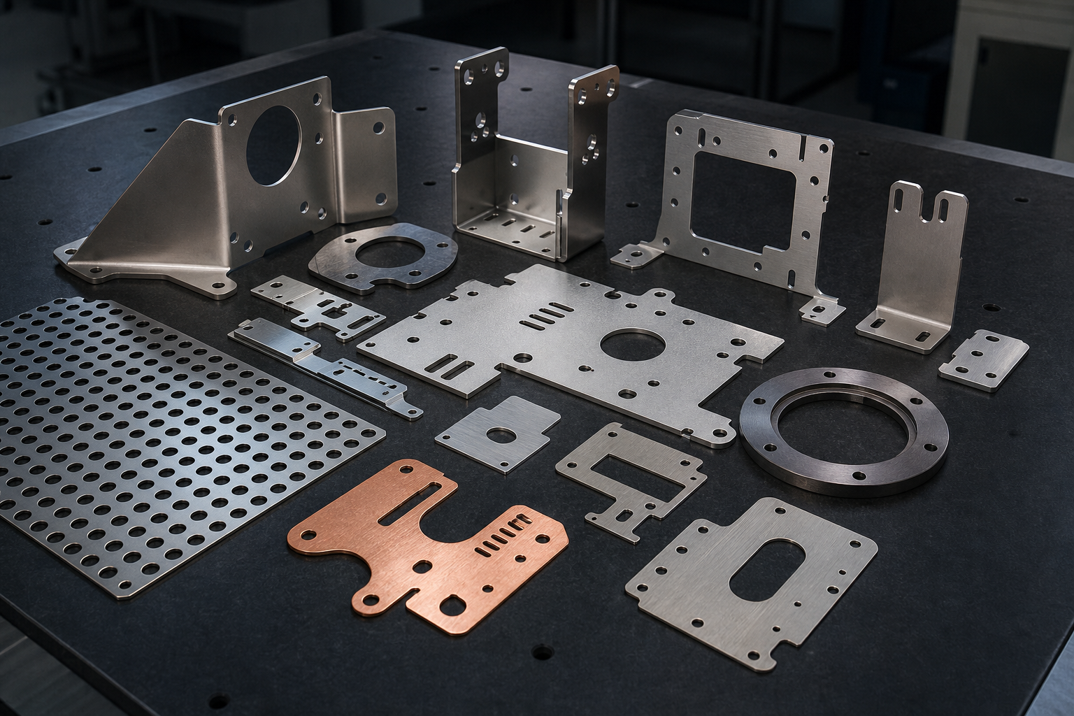
Possible DFM responses include increasing stiffness where function permits, balancing material removal, changing orientation, revising non-critical perforations, adding formed flanges or identifying a planned levelling or machining stage. Every change must be checked against structural, thermal, cosmetic and assembly requirements. See our sheet metal laser cutting design guide for holes, slots, tabs and edge distance.
How Can Flatness Risk Be Reduced?
The objective is controlled, repeatable production—not a claim that distortion can always be eliminated. The appropriate controls depend on part function and quantity.
- Review incoming material: identify obvious wave, coil set, damage and lot-to-lot variation.
- Choose an appropriate material route: material form, temper and supplier specification can affect stability.
- Evaluate nest orientation: long parts and repeated features may respond differently across rolling or levelling directions.
- Plan the sequence: distribute heat and avoid releasing a flexible profile too early where the validated process supports it.
- Manage internal features: dense holes and long slots may require a different order from the outer profile.
- Use support deliberately: microjoints or tabs can retain parts, but they leave removal and finishing points.
- Control unloading: allow appropriate cooling and support thin parts across their area.
- Separate production stages: inspect after the stage that matters to the customer.
- Validate correction methods: rolling, pressing, levelling or machining can have consequences for surface and stress.
- Record first-article results: preserve material lot, orientation, program revision and inspection condition for repeat work.
How to Specify Sheet Metal Flatness on a Drawing
“Keep flat” or “must be flat” is not a complete, inspectable requirement. A useful specification defines what is controlled, when it is checked and how the part is supported.
Flatness versus an assembly requirement
Flatness controls the form of one surface. It does not automatically control parallelism to another face, location relative to a frame or the gap after bolts are tightened. If the real requirement is seal compression, guide alignment, non-rocking support or contact with a reference frame, include the appropriate assembly information.
Apply tight controls selectively
Do not apply the same flatness tolerance to every surface by default. A cosmetic cover and a precision mounting plane serve different functions. Tighter control may require material selection, process development, straightening, machining and more detailed inspection, all of which affect cost.
How to Inspect Sheet Metal Flatness
Inspection begins by defining the part condition. In a free-state check, the part is not forced into shape by unspecified clamps. In a restrained check, it is measured under a documented fixture, fastening or assembly condition. These results answer different questions and should not be substituted for each other.
| Method | Useful application | Important limitation |
|---|---|---|
| Surface plate and indicator | Height variation on suitable small and medium parts | Support, orientation, probe spacing and burr can affect the result. |
| Straightedge and feeler gauge | Quick workshop screening for local gaps | Does not fully characterise the entire surface or minimum-zone flatness. |
| Height gauge or scanning probe | Defined point grid across a surface | Grid density and reference-plane calculation must be agreed. |
| CMM | Documented surface points and relationships to other features | Fixturing, strategy, uncertainty and flexible-part behaviour matter. |
| Optical or laser scanning | Visualising form across a larger area | Filtering, point density and fitting method affect interpretation. |
| Functional fixture | Repeat assembly or go/no-go verification | Demonstrates the defined fixture condition, not necessarily free-state flatness. |
A practical inspection sequence
- Confirm the controlled surface and manufacturing stage.
- Remove debris and address burr that would invalidate support.
- Allow the part to reach the defined measurement condition.
- Support it using the agreed free-state or restrained arrangement.
- Measure enough points to represent the required surface.
- Apply the agreed evaluation method and acceptance rule.
- Record orientation, support, equipment and result where a report is required.
A measurement instrument’s display resolution is not the same as guaranteed measurement uncertainty. The method must be appropriate for the tolerance, size, flexibility and risk of the part. See our quality assurance page for the wider inspection approach.
Flatness After Bending, Welding and Finishing
CNC bending
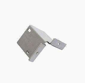
Bend radius, tooling, material variation and springback can change the completed part. A flat laser-cut blank may become an out-of-square or twisted formed component, while a mildly curved blank may be constrained by a correctly designed bend. Define acceptance on the state that performs the final function. Our CNC bending and folding service covers this downstream stage.
Welding and assembly
Weld heating, cooling contraction, joint placement, fit-up, sequence and restraint can produce additional distortion. TWI notes that restraint can reduce movement while increasing residual stress, so “more clamping” is not a universal solution. Critical welded mounting faces may need a planned inspection or machining stage after assembly. See our welding and structural assembly capability.
Coating, grinding and correction
Grinding, blasting, coating cure and mechanical correction may affect thin or flexible components. Straightening should be a controlled operation with an agreed result; it is not evidence that all residual stress has disappeared. Cosmetic surfaces also require protection against tool marks and handling damage.
Application-Based Flatness Decisions
| Application | Why flatness matters | What to define |
|---|---|---|
| Automation mounting panel | Sensors, rails and brackets must align with mating equipment. | Functional face, datums, restrained condition and final hole relationships. |
| Semiconductor-support hardware | Large thin panels may combine appearance, equipment alignment and handling controls. | Material, visible face, protection, inspection stage and documentation. |
| Electrical or machine enclosure | Door fit, seal compression and hardware alignment depend on final formed geometry. | Post-bend or post-coating acceptance and functional gap. |
| Welded frame component | A flat blank can move during joining and fixture release. | Pre-weld condition, final assembly datums and any post-weld machining. |
| Decorative cover | Reflections can make slight wave visually obvious even when assembly is acceptable. | Viewing face, finish direction, sample and appearance criteria. |
For equipment frames, guards, brackets and panels, visit our industrial automation application page and semiconductor and electronics application page.
Singapore RFQ Checklist for Flat Laser-Cut Parts
For Singapore projects, flatness often affects local assembly rather than cutting alone. A panel may need to align with imported linear guides, purchased seals, fasteners or an existing machine frame. Share the full manufacturing and assembly context at quotation stage.
Frequently Asked Questions
Why does sheet metal warp after laser cutting?
Possible causes include incoming sheet shape, residual stress released when material is removed, localised heat, loss of part stiffness, cut sequence and handling. Later bending or welding can introduce additional distortion, so the observed shape rarely proves one cause by itself.
Does laser cutting always cause sheet metal distortion?
No. Laser cutting is a relatively localised, low-heat-input process, and many parts remain suitable without correction. Distortion risk depends on material, thickness, geometry, stress state, thermal conditions and handling; zero distortion should not be assumed for every part.
Can residual stress be released during laser cutting?
Yes. Rolling, levelling, slitting and previous processing can leave residual stress in sheet metal. Removing material changes stiffness and restraint, allowing the stress to redistribute and the cut part to adopt a different shape.
How is sheet metal flatness inspected?
Methods can include a surface plate and indicator, a defined point grid, CMM or scanning, or a functional fixture. The drawing should identify the surface, tolerance, manufacturing stage, support method and whether measurement is free-state or restrained.
Is flatness included in normal dimensional tolerances?
Not automatically. Length, width and hole tolerances control different characteristics. If surface form affects sealing, alignment, contact or assembly, specify the flatness or appropriate functional requirement separately.
Can warped laser-cut parts be straightened?
Some parts can be mechanically levelled, pressed, rolled or corrected using a validated process. Suitability depends on material, geometry, surface requirements and final function. Straightening can have consequences and does not prove that residual stress has been eliminated.
What should I specify for flat laser-cut parts in Singapore?
Provide the controlled surface, flatness tolerance, material, thickness, finished geometry, inspection stage, free or restrained condition, support or fixture details, downstream bending and welding, quantities, reporting and final assembly requirements.
Review Flatness Before Production
Send the DXF or STEP file, material, thickness, quantities, controlled surface and final assembly condition. We can review flatness risk as part of the complete sheet-metal cutting and fabrication route.
Technical references: ISO 1101:2017; ISO 12781-1 flatness terminology; TWI, Laser Cutting and Factors Affecting Distortion; SSAB, product-specific before- and after-cutting flatness example. References support general principles; finished-part acceptance depends on the agreed drawing, material, process and inspection method.