Fiber laser cutting is usually the preferred starting point for sheet-metal parts because metals absorb its near-infrared wavelength efficiently, especially at thin and medium gauges. CO₂ laser cutting is generally the better fit for acrylic, wood, paper, fabric and many other non-metals because those materials absorb its longer infrared wavelength well. Neither process is universally “better”: material, thickness, edge requirement, production volume and the supplier’s actual equipment determine the most economical route.
Fiber and CO₂ lasers can both produce accurate profiles, but they do not interact with materials in the same way. A comparison that ignores wavelength, material grade, thickness and edge-quality requirements can lead to the wrong purchasing decision—or to a quotation that looks attractive but cannot meet the drawing.
This guide focuses specifically on fiber laser vs CO₂ laser cutting. If you need to compare marking, micro-processing and heat-sensitive applications as well as cutting, use our broader Fiber vs CO₂ vs UV laser selection guide.
Fiber vs CO₂ Laser Cutting: Quick Comparison
| Decision factor | Fiber laser | CO₂ laser |
|---|---|---|
| Typical wavelength | About 1.06 μm | About 10.6 μm |
| Common material fit | Stainless steel, mild steel, aluminium, brass, copper and other metals | Acrylic, wood, MDF, paper, fabric, leather and selected polymers |
| Thin-sheet metal productivity | Usually strong because metals absorb the wavelength efficiently | Generally less productive than a comparable modern fiber system |
| Reflective metals | Modern systems are commonly used for aluminium, brass and copper, subject to machine capability | Less commonly selected; actual suitability depends on equipment and setup |
| Clear acrylic edge | Not normally the preferred production route | Often produces the polished-looking edge associated with laser-cut acrylic |
| Maintenance profile | Solid-state source and beam delivery generally reduce optical maintenance | More beam-path optics and gas-system maintenance are typically involved |
| Best purchasing question | Which process can meet this material, thickness, tolerance and edge requirement at the required quantity? | |

Why Wavelength Changes What Each Laser Can Cut
The key difference is not the name on the machine. It is the wavelength of the laser energy and how strongly the workpiece absorbs it.
Fiber laser: near-infrared energy for metals
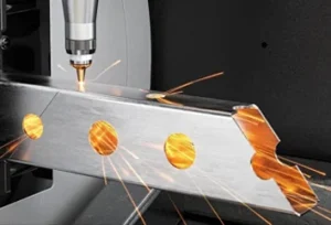
A fiber laser typically operates near 1.06 μm. Many engineering metals absorb this wavelength effectively, allowing a small focused spot and high power density. That combination supports narrow kerfs, detailed profiles and productive cutting—particularly on thin and medium sheet.
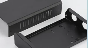
This is why fiber laser metal cutting is commonly considered for stainless-steel enclosures, mild-steel brackets, aluminium panels, electrical parts, machine covers and precision sheet-metal components.
CO₂ laser: longer infrared energy for many non-metals
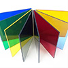
A CO₂ laser typically operates near 10.6 μm. Acrylic, wood, MDF, paper, fabric and many organic materials absorb this wavelength well. On cast acrylic, the process can create the clear or flame-polished-looking cut edge that designers often expect from laser-cut display parts and signage.
CO₂ systems have also been used for metal cutting, particularly before high-power fiber machines became widespread. They may remain technically capable in specific equipment and thickness ranges, but a buyer should compare the supplier’s available machines rather than assume that an older technology rule applies to every modern job.
Material Selection Matrix
| Material | Usual starting point | Important qualification |
|---|---|---|
| Stainless steel | Fiber laser | Thickness, assist gas and required oxide condition affect edge quality and cost |
| Mild / carbon steel | Fiber laser for most current sheet-metal work | Thick plate capability depends heavily on power, gas strategy and supplier equipment |
| Aluminium | Fiber laser | Alloy, thickness, surface condition and reflection-control capability matter |
| Brass and copper | Fiber laser with suitable machine protection and parameters | Reflectivity and thermal conductivity make supplier experience important |
| Acrylic / PMMA | CO₂ laser | Cast and extruded acrylic can produce different edge and engraving results |
| Wood and MDF | CO₂ laser | Resin, moisture and surface finish affect charring and colour |
| Paper, card and fabric | CO₂ laser | Flammability, fumes and edge discolouration require material trials |
| Unknown polymer or composite | Supplier review and sample test | Some materials release hazardous fumes or react poorly to thermal cutting |
For non-metal projects, use a supplier that reviews the exact polymer, adhesive, coating or laminate—not just the generic material name. Our non-metal cutting service covers acrylic, wood and other suitable materials, while specialised films and technical substrates may require a different laser source or process.

Speed and Thickness: Why Generic Numbers Mislead
It is tempting to ask, “How many metres per minute can the machine cut?” That number is only meaningful when the comparison uses the same material grade, thickness, machine power, assist gas and edge-quality requirement.
As a practical trend:
- Thin metal sheet: fiber laser usually offers a productivity advantage because of absorption efficiency and focused power density.
- Medium metal thickness: fiber remains a common production choice, but the difference depends on machine power and gas consumption.
- Thick metal plate: both machine capability and acceptable edge quality become more important than the technology label. Modern high-power fiber systems have expanded this range significantly.
- Non-metals: CO₂ is usually the relevant comparison for acrylic, wood, paper and fabric; a metal-cutting speed table does not apply.
Edge Quality, Kerf and Heat Input
Metal edges from fiber laser cutting
On suitable sheet metal, fiber cutting can produce narrow kerfs and accurate details. Edge condition still depends on focus, nozzle alignment, gas selection, thickness and material consistency. A part that will be welded may have a different acceptable edge standard from a visible enclosure panel or a precision locating feature.
If the drawing requires burr-free handling edges, cosmetic faces or oxide-free weld preparation, state those requirements in the RFQ. “Laser cut” by itself does not define the final deburring or surface-finish standard.
Acrylic and wood edges from CO₂ cutting
CO₂ cutting is valued for acrylic because the cut surface can appear smooth and glossy when the material, focus and speed are properly matched. Cast and extruded sheets respond differently, and excessive heat can cause local melting, flame marks or dimensional variation.
Wood and MDF normally show a darker edge because the process thermally decomposes the material. The amount of charring varies with species, resin content, thickness, moisture and air extraction. A sample is the most reliable way to approve a decorative result.
Describe the required result
“SS304, 2 mm, nitrogen cut, handling edges deburred, visible face protected, hole position per drawing.”
Specify only the machine type
“Fiber laser cut, best quality.” This does not define gas, burr, oxide, protective film or inspection requirements.
Energy, Maintenance and Part Cost
Machine efficiency matters, but buyers ultimately pay for completed parts—not for the laser source in isolation. A useful cost comparison includes:
- Cutting cycle: contour length, piercing, acceleration and small-feature density.
- Assist gas: gas type and consumption can materially change metal-cutting cost.
- Material utilisation: nesting efficiency and minimum web spacing affect sheet yield.
- Machine and optical maintenance: the supplier includes these operating costs in its rate.
- Secondary operations: deburring, oxide removal, polishing, bending and inspection may cost more than the cutting difference.
- Batch size: programming and setup are spread across more parts at production quantities.
Fiber systems generally offer a favourable electrical and maintenance profile for metal production compared with traditional CO₂ metal-cutting systems. CO₂ remains commercially strong where it processes compatible non-metals efficiently and produces the required edge directly. For a broader breakdown of quotation drivers, see our laser cutting cost guide for Singapore.
Which Laser Process Should You Choose?
Start with fiber laser cutting when:
- The part is stainless steel, mild steel, aluminium, brass or copper.
- Thin- or medium-gauge sheet productivity is important.
- The geometry includes detailed profiles, slots and small features.
- You need a supplier focused on metal fabrication and downstream bending or welding.
Start with CO₂ laser cutting when:
- The part is acrylic, wood, MDF, paper, fabric or another confirmed compatible non-metal.
- A polished-looking acrylic edge is part of the design requirement.
- Decorative shapes or signage are being produced without hard tooling.
- A material sample can be approved for colour, charring or edge appearance.
Some projects contain both metal and non-metal components. In that case, the right supplier may use fiber for the sheet-metal parts and CO₂ for acrylic panels, labels or packaging components. The machines are complementary rather than direct substitutes.
What to Send for an Accurate Quotation
1. CAD file: DXF/DWG for 2D profiles; STEP plus PDF drawing for formed or assembled parts
2. Material: exact grade, thickness, colour, coating and protective-film requirements
3. Quantity: prototype and production quantities listed separately
4. Tolerances: general tolerance plus critical dimensions and hole positions
5. Edge condition: burr, oxide, charring, gloss or cosmetic expectations
6. Secondary work: bending, welding, tapping, engraving, polishing or coating
7. Inspection: dimensional report, material certificate or other documentation
8. Delivery: required date and Singapore delivery location
If you are comparing suppliers, send the same complete package to each one. That creates a fair comparison of process, quality and total delivered cost. Our laser cutting buyer’s guide explains the other questions worth asking before placing an order.
Frequently Asked Questions
Is fiber laser cutting always faster than CO₂?
No. Fiber is generally faster and more efficient on thin sheet metal, but actual speed depends on material, thickness, power, assist gas, geometry and quality settings. For non-metals such as acrylic and wood, CO₂ is usually the relevant production process.
Can a CO₂ laser cut metal?
Suitable industrial CO₂ systems can cut certain metals. However, modern fiber lasers are now widely preferred for many sheet-metal applications because of absorption efficiency, productivity and maintenance advantages. Supplier equipment and the required edge remain decisive.
Can a fiber laser cut acrylic or wood?
A standard metal-cutting fiber laser is not normally selected for acrylic or wood because those materials do not absorb its wavelength in the same useful way. CO₂ cutting is generally the more appropriate starting point for these materials.
Which laser is better for aluminium, brass and copper?
Fiber laser systems with suitable reflection protection and process parameters are commonly used for these metals. Thickness, alloy, thermal conductivity and the supplier’s machine capability must still be reviewed before production.
Which process gives a better cut edge?
There is no single answer across all materials. Fiber can produce precise metal profiles, while CO₂ can produce a smooth, glossy edge on suitable acrylic. The acceptable edge must be defined for the actual material, thickness and downstream use.
Do I need to choose the laser type before requesting a quote?
No. Specify the material, thickness, geometry, quantity, tolerance and edge requirement. A qualified supplier should recommend the appropriate process and identify any sample-testing requirement.
Need Help Choosing the Right Cutting Process?
Send your drawing, material, thickness and quantity. We will review whether fiber laser, CO₂ laser or another process is the best fit for the required part.