Data Matrix marking on aluminium—also spelled aluminum—depends on the finished surface, not only the base metal. Bare, brushed, anodized, painted and powder-coated aluminium can require different laser interactions, process sequences, lighting and acceptance methods. A code that appears dark to the eye may still read inconsistently under a production camera.
Quick answer
Bare aluminium, anodized aluminium and coated aluminium should not be treated as one marking condition. Bare metal may rely on a controlled surface or texture change. An anodized part may be marked by changing or selectively removing the surface layer. A painted or powder-coated part may be marked within the coating or by removing it to reveal the substrate. The final route must be validated with the actual alloy, finish, code size, reader, lighting and lifecycle requirement.
A phone scan is useful for an initial check, but it is not the same as production-reader testing or standards-based DPM verification. For project review, see our laser engraving and industrial marking service in Singapore.
Why Is a Data Matrix Different from a Logo or Serial Number?
A human-readable logo or serial number can remain understandable despite modest variation in line width, colour or surface texture. A Data Matrix symbol must also preserve a defined two-dimensional pattern for a camera. The encoded string, finder pattern, individual cells, surrounding clear area and optical contrast all affect performance.
ISO/IEC 16022:2024 defines the Data Matrix symbology, including symbol characteristics, data encodation, formats, dimensions, error correction and quality requirements. The standard applies regardless of whether the symbol is printed, etched, engraved or produced by another marking technology. The application must still define the data, size and acceptance route.
| Requirement | Logo or text | Data Matrix symbol |
|---|---|---|
| Primary reader | Human eye | Camera or two-dimensional imager |
| Data correctness | Usually checked visually | Decoded string must match the approved record |
| Local mark variation | May remain understandable | Can affect cell recognition, modulation or fixed-pattern quality |
| Clear surrounding area | Driven mainly by appearance | Quiet zone must follow the applicable specification |
| Acceptance | Visual sample or drawing | Position, decode, data and—where required—formal verification |
For the wider choice between QR Code, Data Matrix and serial numbering, read our permanent industrial traceability marking guide. This page focuses specifically on how aluminium surface condition changes the marking decision.
Start with the Final Aluminium Surface
“Aluminium” is not a complete marking specification. The RFQ should identify the alloy and temper, but it should also define what the laser will encounter when the part is marked. Rolling marks, brushing, blasting, polishing, anodizing, paint and powder coating change how light interacts with the surface.
| Final surface | Possible marking approach | Main items to validate |
|---|---|---|
| Bare mill-finish aluminium | Controlled surface, texture or shallow material change | Alloy response, reflectivity, contamination, contrast and heat input |
| Brushed or polished aluminium | Mark developed against a directional or reflective background | Grain direction, glare, viewing angle and reader lighting |
| Clear anodized aluminium | Surface-layer change or selective removal, depending on the system | Low visible contrast, substrate reflection, layer condition and sealing |
| Coloured anodized aluminium | Colour change or local removal of the anodized surface | Colour, thickness, batch variation, edge definition and exposed substrate |
| Powder-coated aluminium | Mark in the coating or selectively remove it | Coating chemistry, colour, removal residue and corrosion implications |
| Painted or multi-layer finish | Surface change or removal through one or more layers | Layer stack, charring, adhesion, colour and underlying primer |
Data Matrix Marking on Bare Aluminium
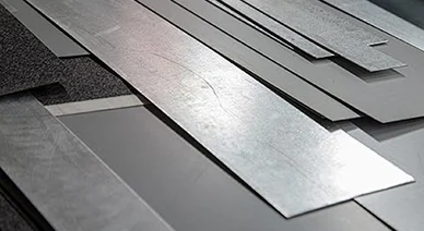
Bare aluminium can be challenging because the background may be bright and directionally reflective. A visually strong mark under diffuse room light may lose apparent contrast when a camera sees glare from the surrounding metal. Conversely, a mark that looks modest to a person may decode reliably with controlled illumination.
The achievable appearance depends on the actual alloy, temper, surface preparation, laser source, optics, focus, pulse behaviour and process parameters. Mill finish, brushed sheet, machined faces and bead-blasted aluminium should therefore be treated as different surfaces even when the alloy designation is the same.
What should be controlled?
- Remove or account for oil, coolant, adhesive, protective film and handling residue.
- Keep the approved surface direction consistent where brushing or machining is visible.
- Evaluate both the cells and the surrounding background under the intended lighting.
- Check whether mark depth, edge relief or local roughness is acceptable for the part function.
- Inspect thin or appearance-critical parts for local distortion, halo or surface damage.
- Record the material lot or surface route when repeatability is important.
Data Matrix Marking on Anodized Aluminium
Anodized aluminium is often selected for panels, housings, nameplates and equipment parts because it combines a controlled appearance with a converted surface layer. That layer is part of the final system. Laser marking may change its colour or structure, or may remove enough of it to reveal a different-looking substrate. Those routes are not automatically equivalent in appearance or environmental behaviour.
| Project condition | Why it matters | What to confirm on a sample |
|---|---|---|
| Black or dark anodizing | A light mark can create strong visual contrast | Cell uniformity, edge definition, substrate exposure and batch stability |
| Clear anodizing | Background and marked area may both remain reflective | Lighting, camera angle, surface texture and repeatability |
| Coloured anodizing | Different dyes and shades may respond differently | Final colour, contrast, halo and approved visual boundary |
| Sealed surface | Sealing condition influences the final layer and use environment | Whether marking changes the agreed surface performance |
| Appearance-critical face | A readable code can still fail cosmetic acceptance | Mark location, orientation, edge quality and surrounding discolouration |
| Outdoor or chemical exposure | The marked area may experience a different lifecycle from the unmarked finish | Post-mark exposure test and the customer’s acceptance requirement |
Do not describe anodized aluminium as universally easier to mark. Dark anodized finishes often provide useful visual contrast, but the real requirement may be machine readability, cosmetic consistency, corrosion behaviour or all three. Approve the result against the final drawing and lifecycle.
Marking Painted and Powder-Coated Aluminium
A coated aluminium part introduces another variable: the laser may interact mainly with the coating rather than with the metal. One route changes the surface of the coating. Another removes coating locally so that the base metal becomes part of the optical contrast. The choice affects appearance, cleanliness and the protective system.
Possible defects include incomplete removal, melted residue, charring, a rough cell boundary, discoloration outside the code, loss of adhesion or inconsistent contrast across a textured coating. A sample should be produced using the actual colour and coating system.
Should the Code Be Marked Before or After Anodizing or Coating?
The correct stage depends on what the code must identify. An in-process code may only need to survive the next operation. A customer-facing traceability code usually needs to remain readable after the complete production route.
| Sequence | Possible advantage | Main risk | Recommended validation |
|---|---|---|---|
| Mark bare aluminium, then anodize | The mark enters the surface-treatment route with the part | Anodizing may reduce, cover or alter the intended contrast | Evaluate only after the final anodizing and sealing process |
| Anodize, then mark | Parameters are developed against the final colour and surface | The laser may change or locally remove the anodized layer | Check readability, appearance and environmental requirement |
| Mark before powder coating | Useful for temporary process tracking | The final coating may obscure the code completely | Confirm whether the code is temporary or must survive coating |
| Coat, then mark | The code is created against the final colour | Coating removal can expose metal or affect the protective system | Test coating edge, substrate, readability and lifecycle |
For a wider process-sequence comparison across metals and treatments, see whether parts should be laser marked before or after coating and heat treatment. The acceptance point should be the stage that represents the delivered part.
Cell Size, Quiet Zone and Marking Area
Data content drives symbol geometry. Adding a long serial number, date, lot, part number and separator structure can increase the number of cells needed. If the available area stays fixed, the individual cells may have to become smaller—and smaller cells increase sensitivity to focus, surface texture, coating variation, contamination and reader optics.
Plan these items together
- Encoded data: define the maximum production string, not only a short sample.
- Cell or module size: use the largest practical size that fits the data and part.
- Quiet zone: keep the required surrounding area free of text, edges, holes, fasteners and other graphics.
- Mark orientation: consider part presentation, camera mounting and fixture repeatability.
- Available area: account for tolerances in both the part and the marking fixture.
- Human-readable data: place text without invading the symbol or its clear area.
If GS1 identification applies, follow the current GS1 specifications for data structure, X-dimension, quiet zone and quality. Do not take a GS1 dimensional table and apply it automatically to every internal non-GS1 code. GS1 guidance also warns that very small modules can reduce symbol effectiveness and require specialised readers.
Curved, Thin-Wall and Small Aluminium Parts
Holes, corners, fasteners and part edges can also interrupt the quiet zone or create glare. If the code will be read after assembly, test it in the assembled orientation rather than only on a loose part positioned conveniently on a bench.
Visual Inspection, Decoding and DPM Verification
These activities answer different questions. Treating them as interchangeable is one of the most common causes of weak acceptance criteria.
| Check | What it demonstrates | What it does not demonstrate |
|---|---|---|
| Visual inspection | The mark exists, is in the expected location and broadly meets appearance requirements | That the encoded string can be decoded |
| Phone scan | One consumer device decoded the code under one condition | Production-reader performance or a formal quality grade |
| Production-reader test | The intended camera can read the symbol in the tested work-cell setup | Standards-based grading unless the equipment and method provide it |
| DPM verification | Symbol quality is measured using the stated standard, lighting and configuration | That the decoded business data is correct or registered in a database |
| Data validation | The decoded string matches the required syntax, sequence and record | That the physical mark will survive its full lifecycle |
ISO/IEC 29158:2025 addresses direct part mark quality testing. It recognises that DPM surfaces can produce specular reflection and that direct marking may not behave like a conventional printed symbol. This is particularly relevant to bright, polished or directional aluminium, where illumination angle can change the captured image substantially.

Our separate guide explains how to verify laser-marked Data Matrix codes, including the difference between reading, verification and data validation.
Define Durability Through the Actual Lifecycle
“Permanent” is not an unlimited promise. The useful requirement is whether the mark remains acceptable after the exposures that matter to the part.
| Exposure | Possible concern | Acceptance question |
|---|---|---|
| Cleaning agents or solvent wiping | Coating change, residue or loss of contrast | Must the code decode or retain a specified grade after a defined cycle? |
| Abrasion and handling | Cell edges wear or the reflective background changes | What contact, load, material and number of cycles represent use? |
| Coolant, oil or process residue | Contamination masks cells or changes reflection | Will the code be read clean, contaminated or after a controlled cleaning step? |
| UV or outdoor exposure | Coating colour and contrast can age | What exposure duration and pass condition apply? |
| Humidity or coastal environment | Exposed substrate or damaged coating may behave differently | Does the marked area need a project-specific corrosion evaluation? |
| Later fabrication or assembly | The code may be covered, scratched or placed outside the camera view | At what manufacturing stage and orientation is it accepted? |
Singapore equipment projects may combine local assembly with imported readers, coatings or purchased parts. Define the final reading location, cleaning practice and environmental exposure at quotation stage rather than assuming a laboratory scan represents field performance.
When Is a Representative Sample Required?
A practical approval workflow
The approved sample should represent the production alloy, surface supplier, colour, geometry, mark size and orientation. Retain the encoded data, parameter revision, reader setup and acceptance result so repeat production is compared against a controlled baseline.
Singapore RFQ Checklist for Aluminium Data Matrix Marking
A useful quotation needs more than a drawing with a small square labelled “QR”. State the actual symbology, data and acceptance requirement.
Typical uses include equipment panels, housings, fixtures and replaceable components for industrial automation projects, as well as aluminium parts and equipment identification for semiconductor and electronics applications. The application does not replace the need to define the final surface, code data and acceptance method.
Frequently Asked Questions
Can a Data Matrix be laser marked on bare aluminum?
Yes, many bare aluminium parts can be marked, but the result depends on alloy, temper, mill or machined finish, contamination, code size and laser process. Bright or directional surfaces also require appropriate lighting. Approve the mark using the actual production reader and part condition.
Is anodized aluminium easier to laser mark?
Some anodized colours can provide strong visual contrast, but anodizing is not one uniform surface. Type, colour, thickness, sealing and batch variation affect the result. The mark may alter or remove part of the anodized layer, so readability, appearance and lifecycle requirements should all be tested.
Should a Data Matrix be marked before or after anodizing?
Either sequence may be possible. Marking before anodizing risks the later process changing or covering the code. Marking after anodizing develops the result on the final surface but may modify the anodized layer. Test the complete manufacturing route and verify at the delivered stage.
Can a Data Matrix be marked on powder-coated aluminium?
Potential routes include changing the coating surface or selectively removing coating to expose a contrasting layer. Suitability depends on the coating chemistry, colour, thickness and protective requirement. Check residue, edge quality, adhesion, exposed substrate and durability using the actual coating system.
Is a successful phone scan enough to approve a DPM code?
No. It only shows that one phone decoded the symbol under one condition. A production-reader test checks the intended camera setup, while formal DPM verification measures symbol quality using a defined standard, illumination and configuration. Data correctness and lifecycle durability also need separate acceptance.
What information is needed to quote aluminium Data Matrix marking?
Provide the alloy, final surface and colour, part geometry, marking area, encoded data and maximum length, code size, quantity, actual reader, applicable standard, grade if required, lifecycle exposure and whether a verification report or approved sample is needed.
Review Your Aluminium Data Matrix Project
Send the drawing, alloy, final surface, code data, available marking area, quantities and reading requirements. We can review the process route and recommend a representative sample before repeat production.
Technical references: ISO/IEC 16022:2024, Data Matrix symbology specification; ISO/IEC 29158:2025, Direct Part Mark quality test specification; GS1 DataMatrix Guideline. The applicable standard, data structure, size, illumination and grade must be defined by the customer or governing project specification.