

Quick answer: Before ordering a custom copper busbar blank, identify whether the supplier must deliver a flat cut part or a finished bent part. The approved drawing should define the copper grade and temper, hole datums, bend orientation and final dimensions, conductive contact faces, surface treatment and the stage at which each feature will be inspected. Cutting a correctly shaped copper part does not establish its electrical rating or certify the assembly.
In this guide
For a Singapore panel builder, equipment maker or maintenance buyer, “make this copper busbar” is not yet a complete manufacturing instruction. A flat profile may fit its DXF while the later bend moves a connection hole away from its mating terminal. An unmarked contact area may be handled or finished like an ordinary cosmetic face. This guide turns those hand-off risks into drawing and quotation checks for custom copper busbar blanks and bent parts.
It addresses drawing-led component manufacture. The customer’s responsible electrical designer remains responsible for conductor sizing, joint design, clearances and the completed system.
Start by Naming the Deliverable: Flat Blank or Bent Part
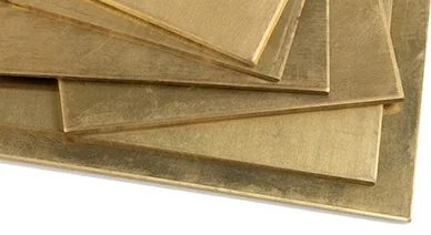
In this article, a blank is the flat cut profile before forming. A part supplied with one or more finished bends is a formed part. Specify which state the purchase order requires; do not leave the supplier to infer it from a flat file.
| Order state | Define in the RFQ | Acceptance focus |
|---|---|---|
| Flat cut blank | Approved outline, thickness, holes and slots; downstream bending or assembly performed elsewhere. | Flat dimensions, hole location, cut-edge and contact-face condition in the delivered state. |
| Finished bent part | All blank requirements plus bend direction, radius, angles, final geometry and any left/right orientation. | Critical installation dimensions and mating-hole alignment after forming, not just the flat pattern. |
| Part requiring a specified finish | Whether treatment is required, where it starts and stops, and which contact faces must remain in the approved condition. | Finished-state checks only for operations explicitly included and agreed in the quotation. |
The process route follows the part. Sheet metal laser cutting may produce a suitable flat copper profile, while a formed order also needs a copper bending feasibility review. Thickness, temper, geometry and tooling access must be confirmed for the individual drawing; a published general range is not approval of every busbar design.
State the Copper Specification and Condition
Give the full material grade and standard, temper, thickness and required product form. Do not rely on the word “copper” or an ambiguous short grade name. State whether a material certificate or substitution approval is required. The copper material page explains grade and temper selection in more detail; this article focuses on turning an approved choice into a manufacturable order.
Material condition matters at the bend and during handling. The bend radius and forming route should be reviewed for the specified copper and temper rather than copied from an unrelated part. The Copper Development Association’s busbar guide shows how bending depends on material condition and dimensions, while joint performance also depends on geometry, surface condition and pressure. Its example radii are engineering references, not a universal Lumen Future capability or an approval to change the customer’s drawing.
Dimension Holes From the Mating Assembly
Show what locates the part during installation. A hole pattern is more useful when its dimensions refer to an identified datum edge, face or mating component than when the drawing provides only an overall length and a chain of approximate pitches. For each mounting or connection feature, identify the hole or slot size, quantity, centre positions, orientation and the face from which the drawing is viewed.
Call out the holes whose position matters to a terminal, fastener or other busbar. State the fit or positional requirement only where the design needs it. A clearance hole may be acceptable directly after cutting; a close-fit feature or demanding hole-edge condition may need a further operation, which must be reviewed and included in the quotation. The site’s copper laser-cutting guide discusses the material-specific cutting background; it does not replace the approved hole specification for this order.
Do not move or enlarge connection holes merely to simplify manufacture. The Copper Development Association notes that holes in a bolted busbar joint alter the current path. Hole number and layout therefore belong to the customer’s approved mechanical and electrical design, not to an unchecked shop-floor adjustment. If a feature is difficult to cut or inspect, raise it for design approval before production.
Separate Flat-Pattern Data From Finished Geometry
For a formed part, provide a finished-part drawing or model showing bend direction, angle, inside radius, orientation of each contact face and the installed relationship to adjacent parts. A flat DXF alone cannot reliably communicate whether a bend goes towards or away from a marked surface. Include the minimum straight sections or tool-clearance restrictions that affect the approved design, and identify left- and right-hand variants rather than assuming they are interchangeable.
Mark the dimensions that must be correct after bending: for example, a terminal-to-terminal spacing, the distance from a mounting face to a hole centre, or the position of a contact pad relative to the enclosure. Indicate where holes close to a bend need a finished-state check. The flat blank may pass inspection while the formed part fails to meet its mating hardware.
A drawing package can use a DXF for the flat profile, a STEP model for the formed shape and a dimensioned PDF for the governing tolerances and notes. Give all files the same drawing number and revision, and state which one controls if they disagree. Review the first formed part when fit, bend appearance or contact-pad alignment is critical; do not assume one fixed bend radius or tolerance works for every copper temper and thickness.
Mark Contact Faces Before Finishing and Packing
Identify each conductive mating area on the drawing, including the side of the part, its boundary and the surface it will meet. State whether it is specified as bare copper or requires a particular coating or plating. Mark any area where polishing, marking, protective film, adhesive labels or other treatment is prohibited. If plating, masking or a specialist electrical check is required, ask for its availability, responsibility and acceptance method to be confirmed in the quote; do not assume it is included in a cutting price.
Agree what “acceptable contact face” means for the actual design: permitted marks, burr condition, contamination, coating boundary and handling protection. A bright appearance alone does not prove a good joint. Contact resistance depends on the condition of both mating surfaces and the pressure applied during assembly, among other design factors. Nor is polishing or tinning automatically appropriate for every joint; some equipment instructions specifically prohibit sanding plated contact surfaces. Follow the approved joint specification rather than a generic finishing rule. See the Copper Development Association’s jointing guidance and a manufacturer’s product-specific assembly instructions.
State how completed parts should be separated, labelled and packed so the agreed contact surfaces and part orientation are preserved through Singapore delivery and assembly. Packaging requirements should be proportionate to the specified finish; they are not a substitute for an inspection criterion.
An Illustrative Drawing-Note Convention
Example only—not a production drawing or electrical design: On a customer-approved PDF, label the mounting edge Datum A and the mating face Datum B. Identify connection holes as H1–H2 with their specified diameters and positions from A/B. Mark the permitted bend line and arrow for its direction, then call out which H1-to-contact-face dimension is checked after bending. Hatch the conductive pad as Contact Area C and state its required delivered finish and no-treatment boundary. The actual values, tolerances and joint design must come from the responsible designer.
That notation gives purchasing, fabrication and inspection the same reference points. It also makes an engineering query straightforward: if a bend moves H2 beyond the approved finished-state tolerance, the team knows which requirement needs review rather than silently altering the flat profile.
Agree First-Off and Delivery Acceptance by Stage
Choose checks for the delivered state, not for a generic “precision copper part”. If first-off approval, batch sampling, a dimensional report or a material certificate is needed, request it before quotation and identify who signs off the result.
| Stage | Possible drawing-led checks | Approval boundary |
|---|---|---|
| After cutting | Outline, specified hole positions, thickness, edge and burr condition, part identification. | Confirms the agreed flat blank; not its eventual assembly fit. |
| After forming, if ordered | Critical finished dimensions, angle, hole-to-mating-face alignment, contact-pad orientation and bend condition. | Confirms the formed component against its drawing; does not prove electrical performance. |
| After specified finishing, if ordered | Coating or plating boundary, protected contact faces, accepted appearance and packing. | Only the checks included in the agreed finishing and inspection scope. |
Component acceptance is not system certification. The customer’s electrical designer or assembly owner must confirm the current rating, temperature rise, fault duty, clearances, fasteners and final joint performance. A fabricated copper part does not, by itself, demonstrate compliance of a completed low-voltage assembly with IEC 61439-1. Any specialist testing or compliance documentation needs a separately agreed scope.
A Practical RFQ Package for Singapore Buyers
Send enough information to distinguish what is already approved from what still needs engineering review:
- Part identity: drawing number, revision, matching assembly reference and quantity per part or set.
- Material: full grade and standard, temper, thickness, product form and any certificate requirement.
- Geometry: dimensioned PDF plus flat DXF; include a finished STEP model or formed drawing where bends are required.
- Critical features: datums, hole and slot pattern, bend direction and radius, finished-state dimensions and left/right variants.
- Contact areas: marked mating faces, specified surface condition, coating or masking boundaries and handling restrictions.
- Acceptance: first-off or sample fit, inspection stage, required report and the person who can approve a revision.
- Delivery: required date, Singapore receiving location, part labels, grouping and packaging.
If you have only a flat sketch or an existing part, say so rather than treating an unverified file as a release-ready electrical design. A feasibility review can identify missing fabrication information, but the owner of the electrical assembly must approve changes affecting fit or performance.
Frequently Asked Questions
Is a flat DXF enough to quote a bent copper busbar?
Usually not by itself. It shows the flat outline but may omit bend direction, final mating dimensions, contact-face orientation and acceptance conditions. Add a finished-part drawing or STEP model and a governing dimensioned PDF.
Can the cutting supplier change a hole layout that is difficult to make?
The supplier can flag a manufacturing concern and propose an alternative. Connection-hole position, size or number should not change without approval from the responsible mechanical and electrical designer.
Does a clean, bright contact pad guarantee electrical performance?
No. Surface appearance is one acceptance item, but the completed joint also depends on the mating component, fasteners, contact pressure and installation. Define any required electrical verification separately.
Request a Copper Busbar Parts Review
Send your approved drawing set, copper specification, quantity and delivery requirement. Mark the holes, bends and conductive contact faces that matter to assembly, and state whether you need flat blanks or finished formed parts. Lumen Future can review the requested fabrication and inspection scope before quoting; electrical design approval remains with your responsible team.