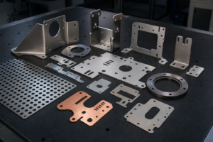
Glass cutting tolerances describe whether a finished profile meets its drawing. Edge quality describes chips, cracks, roughness and other conditions that may affect handling, assembly or reliability. These are related manufacturing outcomes, but they are not interchangeable acceptance criteria.
Quick answer
A glass part can meet its length, width and hole-position tolerances while still having an unacceptable chip or crack. A visually clean edge does not prove that every dimension is within tolerance or that no subsurface flaw exists. Buyers should specify dimensions, datums, permitted edge defects, inspection method, magnification and sampling level separately.
There is no responsible universal tolerance, minimum hole size or chip allowance for every glass composition and thickness. Final requirements should be reviewed against the actual material, geometry, cutting route, edge finish and downstream use. See our precision glass cutting service in Singapore for project-review information.
Glass Cutting Tolerance and Edge Integrity Are Separate Requirements
Dimensional inspection asks where the manufactured boundary is relative to the controlled drawing. Edge inspection asks what condition exists along and below that boundary. Combining both under one general note such as “all dimensions ±0.1 mm, no chips” leaves important questions unanswered.
| Observed result | What it can establish | What it does not establish |
|---|---|---|
| Overall length and width are within tolerance | The measured dimensions comply at the stated datums and method. | It does not prove that the edge is free from chips or cracks. |
| The edge looks smooth to the unaided eye | No large visible defect was observed under those viewing conditions. | It does not prove dimensional compliance or absence of small and subsurface flaws. |
| No crack was found at an agreed magnification | No reportable crack was detected within that method, field and sample. | It is not an unlimited guarantee of zero flaws at every scale. |
| Hole diameter is within tolerance | The measured opening meets its size requirement. | It does not prove that the ligament to the outer edge is strong enough for service. |
The purchase drawing should therefore identify which edges are functional, visible, loaded, bonded, sealed or merely non-critical. A concealed interior edge may only need safe handling and controlled breakout. An optical window, display cover or highly stressed mounting hole may need a more detailed acceptance plan.
Why Do Different Glasses Have Different Cutting Risks?
“Glass” covers materials with different compositions, thermal expansion, hardness, strengthening history and flaw response. A process proven on annealed soda-lime glass should not be treated as automatically qualified for borosilicate, fused silica, chemically strengthened display glass or optical glass.
| Material family | Processing and inspection emphasis | Do not assume |
|---|---|---|
| Soda-lime or float glass | Stock quality, thickness, edge breakout, subsequent tempering and general visual requirements. | Familiar material does not mean every geometry has the same tolerance. |
| Borosilicate glass | Low thermal expansion can support thermal applications, but grade and manufacturing route still matter. | Low expansion does not guarantee chip-free or crack-free edges. |
| Fused silica or quartz glass | High purity and low expansion applications may require specific edge, cleanliness and optical controls. | Settings or acceptance criteria from float glass can be copied directly. |
| Aluminosilicate and display glass | Thin sections, chemical strengthening, coatings, handling and residual-stress state require review. | Strengthened sheets can always be cut after strengthening without consequence. |
| Optical glass | Material identity, optical surfaces, centration, coating protection and edge finish may dominate. | A general fabrication drawing covers every optical requirement. |
| Sapphire | This crystalline material needs its own orientation, edge and defect specification. | It is technically interchangeable with amorphous glass. |
For material-selection questions, see our guides to borosilicate and specialty glass processing and sapphire versus quartz. This article remains focused on dimensional and edge acceptance.
Which Glass Cutting Tolerances Should a Drawing Control?
A useful glass drawing separates stock characteristics from features created during cutting and finishing. Thickness is usually a property of the supplied sheet or blank. Cutting controls the in-plane profile, holes and relative feature positions. Grinding or polishing may then change the final contour.
Machine positioning resolution is not the same as guaranteed finished-part tolerance. The outcome also depends on sheet condition, part size, material response, fixturing, feature geometry, cutting direction, edge finishing, datum strategy and measurement method.
How Should Chips and Visible Edge Defects Be Defined?
“No chipping” is difficult to audit unless the drawing also states the inspection conditions and minimum reportable size. Edge defects should be described by type, width, depth, length, location and permitted quantity.
A practical acceptance note should answer:
- What is the maximum permitted chip width and depth?
- How many defects are permitted per edge or part?
- Are corner defects treated differently?
- Are holes, sealing edges and bonded edges controlled more tightly?
- Is the defect measured at the glass face, through the thickness or both?
- Can the edge be reworked, and how will final dimensions be verified?
Standards for particular glass products may define edge faults, but their scope matters. For example, a building-glass or mirror standard should not be presented as the universal acceptance specification for an optical, semiconductor or laboratory component. The applicable customer drawing and product standard take precedence.


What Is the Difference Between a Chip and a Microcrack?
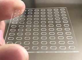
A visible chip is missing material at the edge. A microcrack is a small fracture that may be visible only under suitable magnification or may extend below the surface. Either can matter, but they are not measured or accepted in the same way.
Glass strength is governed by its flaw population rather than by a single fixed material-strength number. Edge and surface flaws may grow under tensile stress, humidity, thermal cycling, bending, impact or assembly load. Corning’s published fracture studies show how scoring can produce surface and subsurface cracks that influence residual edge strength. This is why a clean-looking photograph cannot certify long-term mechanical reliability.
An inspection statement should be bounded:
- the part area examined;
- lighting and preparation conditions;
- instrument and magnification;
- minimum reportable defect size;
- sample quantity or 100% inspection requirement; and
- the acceptance threshold.
What Heat-Affected Conditions Can Occur in Laser-Processed Glass?
Laser processing can involve thermal scribing, controlled fracture, material removal, melting or another mechanism depending on the equipment and material. The possible observations therefore change with the process.
| Observation | What to record | What cannot be concluded from appearance alone |
|---|---|---|
| Thermal crack | Origin, direction, length and whether it enters a functional area. | The precise residual-stress field or future growth rate. |
| Melt ridge or re-solidified material | Height, continuity, sharpness and effect on fit or sealing. | That all subsurface material is unaffected. |
| Rounded or softened edge | Profile change and resulting dimension. | That rounding automatically improves strength. |
| Haze or colour change | Location, lighting, visible area and optical impact. | A quantified heat-affected depth or mechanical property. |
| Local roughness change | Specified roughness parameter and measurement direction when functional. | Crack size or residual strength. |
Polarised-light inspection may reveal stress-related optical effects in suitable transparent materials, but it is not a universal quantitative residual-stress measurement. The method, calibration and material state need to be defined.
How Should Holes, Slots and Edge Distance Be Designed?
Small holes and narrow edge ligaments combine geometry, manufacturing and service-loading risks. A hole close to the outer edge can create a weak bridge of material. Sharp internal corners and narrow slot ends can increase local stress. A mounting hole can pass dimensional inspection and still fail later if a screw, clamp or press fit loads the glass directly.
Do not apply one diameter-to-thickness or edge-distance ratio to every material. Use the following as a DFM review list:
- material family, supplier grade and strengthening condition;
- nominal thickness and stock tolerance;
- hole diameter, slot width and corner radius;
- hole-to-edge and hole-to-hole ligament;
- required position tolerance and datums;
- fastener, gasket, clamp or bonding load;
- as-cut, ground, polished or chamfered edge condition;
- whether the part will later be tempered, coated, bonded or thermally cycled; and
- permitted chips or cracks around the opening.
Where a tight-fit, sealing or heavily loaded hole exceeds the capability of an as-cut condition, the route may include drilling, grinding, lapping or polishing. The drawing should include the material allowance for that secondary operation.
How Do Thin and Thick Glass Change the Risk?
| Consideration | Thin glass | Thick glass |
|---|---|---|
| Handling | Flexure, suction, static, interleaving and local contact can dominate breakage. | Weight, lifting, corner impact and support spacing become important. |
| Fixturing | Vacuum or support must avoid distortion and surface damage. | Flat support and stable positioning are needed over larger mass. |
| Measurement | Contact force may deflect the part; non-contact methods may be preferable. | Measure at defined faces and heights if edge taper or perpendicularity matters. |
| Edge formation | Small flaws can consume a larger fraction of thickness. | Exit condition, thermal path and through-thickness geometry require control. |
| Packaging | Flat support, clean interleaving and bending protection are essential. | Edge guards, separation, impact control and safe weight handling are essential. |
Thin glass is not universally harder to cut, and thick glass is not universally more robust. The dominant failure mechanism changes with geometry, material, process and handling.
How Should Precision Glass Parts Be Inspected?
The inspection method must be capable of resolving the specified requirement without damaging or deforming the part. A steel-rule or hand-caliper check may be reasonable for some general panels but is not a universal solution for thin display glass or precision optical blanks.
| Method | Useful for | Key limitation |
|---|---|---|
| Visual inspection under controlled lighting | Large chips, obvious cracks, scratches, contamination and gross edge irregularity. | Does not prove absence of microcracks. |
| Magnifier or optical microscope | Small chips, crack features and detailed edge texture. | Result depends on magnification, focus, field coverage and sample plan. |
| Vision measuring system or profile projector | 2D profile, hole size, position, radii and coordinate dimensions. | Transparent-edge detection and datum setup must be validated. |
| Non-contact height or displacement measurement | Selected step, thickness, flatness or surface geometry checks. | Reflective and transparent surfaces can require suitable optics and setup. |
| Surface profilometer | Specified roughness and local profile. | Does not replace crack inspection or strength testing. |
| Polarised-light method | Selected stress or birefringence observations in suitable material. | Not automatically quantitative for every glass and geometry. |
| Destructive strength test | Process qualification, batch studies and reliability modelling. | Statistical result; the tested specimen cannot be delivered. |
The report should record the equipment, datum setup, environmental conditions where relevant, sampling quantity and actual result. For critical projects, agree a first article before volume production. Lumen Future’s quality assurance page explains the wider drawing and inspection review process.
When Should a Glass Edge Be Ground or Polished?
Secondary edge finishing may be required for safe handling, visible appearance, sealing, bonding, optical use or improved control of selected surface damage. Common descriptions include as-cut, seamed or arrised, ground, fine-ground, polished, chamfered and bevelled. These terms need an agreed visual or measurable definition.
| Edge condition | Typical reason to specify it | Drawing consideration |
|---|---|---|
| As-cut | Cost-effective where the direct process meets function and handling needs. | Define chip, sharpness and inspection limits. |
| Seamed or arrised | Remove dangerous sharpness from non-cosmetic edges. | Allow for corner and edge material removal. |
| Ground | Control size, improve handling or prepare a more consistent edge. | State final dimensions after grinding. |
| Fine-ground or polished | Visible edges, optical paths, sealing or demanding handling requirements. | Define appearance, roughness or approved sample as applicable. |
| Chamfer or bevel | Assembly clearance, edge protection or load distribution. | Specify angle, width, tolerance and corner transitions. |
Grinding or polishing can remove selected damage and change the edge profile, but it should not be marketed as a guarantee that every crack has been eliminated. Final dimensions and inspection must follow the finishing operation.
Example Glass Drawing and Inspection Notes
The following is a communication example, not a universal Lumen Future tolerance:
CONDITION: annealed / strengthened / coated as applicable
THICKNESS: nominal value and stock tolerance
DATUMS: identify functional datum edges or centre features
PROFILE: controlled dimensions and critical feature positions
EDGE DEFECT: maximum chip size, location and permitted quantity
INSPECTION: agreed visual or microscope method and magnification
SAMPLING: first article, batch sample or 100% as required
EDGE FINISH: as-cut / arrised / ground / polished / chamfered
CRITICAL SURFACES: identify optical, coated, bonded and scratch-sensitive faces
For optical glass and finished optical elements, standards such as ISO 12123 and the ISO 10110 series may support communication, but only when their scope and drawing conventions apply. Do not reference an optical standard solely to make a general fabrication drawing look more precise.
Glass Cutting RFQ Checklist
Send the information needed to review manufacturing and inspection before quoting:
Frequently Asked Questions
What is a typical glass cutting tolerance?
There is no single tolerance for every glass part. Material, thickness, size, feature geometry, cutting route, edge finishing, fixturing and measurement method all matter. The supplier should review the actual drawing before confirming a finished-part tolerance.
Are glass cutting tolerance and edge quality the same?
No. Dimensional tolerance controls size, position or profile. Edge quality controls chips, cracks, roughness and other edge conditions. A part can pass one requirement and fail the other.
What is the difference between an edge chip and a microcrack?
A chip is missing material visible at the edge. A microcrack is a small fracture that may require magnification and may extend below the surface. They need different description and inspection criteria.
Can laser cutting guarantee microcrack-free glass?
No process should be described as universally microcrack-free without a defined detection method and limit. A valid report states the inspected area, magnification, sampling and minimum reportable defect.
What is the minimum hole size in cut glass?
The minimum practical hole depends on glass type, thickness, process, required edge finish and surrounding ligament. A universal diameter-to-thickness rule should only be used for preliminary screening, followed by drawing review.
How close can a hole be to the glass edge?
Required distance depends on thickness, material, hole size, edge finish, cutting process and service load. Fasteners, clamps, gaskets and thermal cycling should be included in the review.
When should a glass edge be ground or polished?
Finishing may be required for safe handling, visible appearance, sealing, bonding, optical use or tighter control of selected edge damage. Final dimensions must be inspected after finishing.
What information is needed for a glass cutting quotation in Singapore?
Provide the exact material, condition, thickness, drawing, quantity, critical tolerances, chip and crack acceptance, inspection method, edge finish, surface protection and packaging requirements.
Request a Glass Drawing and Inspection Review
Send the material grade, thickness, drawing, edge-finish requirement and inspection criteria. Our glass cutting team can review the geometry, glass cutting tolerances, achievable process route and information needed for your Singapore project.
Technical references: Corning, Display Glass Technical Papers, Fracture Behavior and Fracture Analysis; ISO, ISO 12123:2018 Raw Optical Glass and ISO 16293-2:2025 Float Glass. Standards apply only within their stated scope; the controlled customer drawing and agreed inspection plan govern project acceptance.